RD 300-450 F
Ver.1.3 07/06/01
25
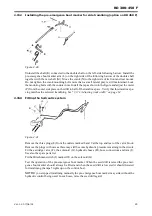
2.15.2
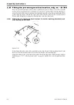
Installing the pre-emergence bout marker for side tramlining (option on RD 450 F)
Figure 2.20
Uninstall the shaft (K) connected to the double shaft on the left-side following harrow. Install the
pre-emergence bout marker arm (L) on the right side of the following harrow of the double shaft
together with the new shaft (M). Move the crank (N) to the right side of its front and rear mount.
Do not tighten the crank mounting bolts more than a small lateral play is still maintained. Lock
the mounting bolts with the counter nuts. Install the tap as shown in the figure and adjust the meter
(P) from the outer side plate on the drill to half of the tramline space. Verify that this tramline spa-
cing matches the selected tramlining. See ”3.17.1 Adjusting track width” on page 64.
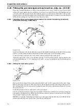
2.15.3 Fitting the hydraulic system
Figure 2.21
Remove the three plugs (E) from the outlets marked 8 and 9 at the top and rear of the valve block.
Remove the plugs with care as there may still be some hydraulic pressure remaining in the circuit.
Fit the cartridge valve (F), the solenoid (G), hydraulic hoses (H), hose connections and ram (I).
See also the spare parts list.
Fit the Hirschman switch (J) marked 20 on the solenoid (G).
Test the operation of the pre-emergence bout marker. When the seed drill is raised the pre-emer-
gence bout marker should always be lifted and when the seed drill is lowered it should lowered
for tramlining (Lamps 5 lights up on the control box).
NOTE!
If you step past tramlining manually the pre-emergence bout marker may sink without the
hydraulic control being used. In such case, raise the seed drill again!
Summary of Contents for RAPID RD F Series
Page 1: ...Ver 1 3 07 06 01 900107 en Instructions Seed drill RAPID series RD 300 450 F No 10 026 11 999...
Page 2: ...2 Ver 1 3 07 06 01...
Page 6: ...6 Ver 1 3 07 06 01...
Page 16: ...Assembly instructions 16 Ver 07 06 01 07 06 01...
Page 23: ...RD 300 450 F Ver 1 3 07 06 01 23...
Page 41: ...RD 300 450 F Ver 1 3 07 06 01 41...
Page 47: ...RD 300 450 F Ver 1 3 07 06 01 47...
Page 108: ...Appendices 108 Ver 07 06 01 07 06 01 7 4 Electrical diagram Figure 7 8 307335...

