RD 300-450 F
Ver.1.3 07/06/01
109
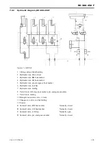
7.4.1
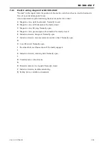
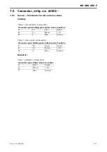
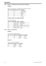
Electric wiring diagram for RD 300-450 F
"Normal" in this regard refers the position of the electric unit when it has no electric load and is
free of any cam and magnetic forces.
Area measurement is performed using the detector on the drive wheel
A
Magnetic valve, right bout marker. Normally closed.
B
Magnetic valve, left bout marker. Normally closed.
C
Magnetic valve, lift stop. Normally open.
D
Magnetic valve, pre-emergence about marker. Normally closed.
E
Inductive detector, fan speed. Normally open.
F
Inductive detector, area measurement on drive wheel. Normally open.
G
H
Low-lift switch. Normally open.
I
Freewheel hub, seed house shut-off. Normally engaged.
J
K
Inductive detector, rotation guard. Normally open.
L
M
Tramline motor, wheel tracks.
N
O
Dielectric detector, level guard. Normally closed.
P
Inductive detector, tramline monitoring
Q
Setting device, variable sown amount
Summary of Contents for RAPID RD F Series
Page 1: ...Ver 1 3 07 06 01 900107 en Instructions Seed drill RAPID series RD 300 450 F No 10 026 11 999...
Page 2: ...2 Ver 1 3 07 06 01...
Page 6: ...6 Ver 1 3 07 06 01...
Page 16: ...Assembly instructions 16 Ver 07 06 01 07 06 01...
Page 23: ...RD 300 450 F Ver 1 3 07 06 01 23...
Page 41: ...RD 300 450 F Ver 1 3 07 06 01 41...
Page 47: ...RD 300 450 F Ver 1 3 07 06 01 47...
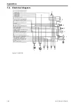
Page 108: ...Appendices 108 Ver 07 06 01 07 06 01 7 4 Electrical diagram Figure 7 8 307335...

