Troubleshooting
96
Ver.07/06/01 07/06/01
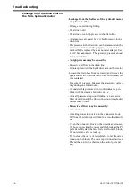
Leakage from the shaft seal on
the fan's hydraulic motor!
- Leakage from the shaft seal of the hydraulic motor
may be caused by:
- Damage caused during fitting.
- Wear due to dirt.
- Wear due to too high pressue in the drain line.
- A damaged seal caused by very high pressure in the
drain line.
- The pressure in the drain line can be measured on the
connector block when the plug (on the connector
marked M) is replaced by a manometer adapter. Use
a 0-10 bar manometer. The operating pressure shoud
not exceed 2 bars
- A high pressure may be caused by:
- Excessive oil flow in the drain line
- Counter-pressure in the hydraulic valve on the tractor.
- Loosen the drain hose from the tractor and remove the
quick connector. Start the fan. Collec the drained oil
in a container.
- Measure the pressure. Measure the amount of oil exi-
ting during one full minute.
- A considerable pressure drop would indicate a pro-
blem with the tractor's hydrauliv valve.
- A small pressure drop would indicate an excessive
flow of oil. Usually the flow in the drain line should
be less than 3 l/min.
- Excessive oil flow may be caused by:
- A worn motor
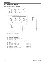
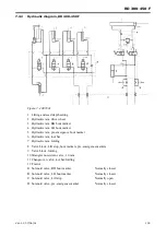
- A leaking non-return valve on the connector block.
Oil from the return line will then leak into the drain li-
ne.
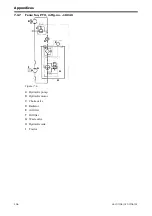
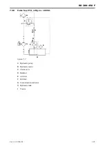
- Clean the connector block on the outside and loosen
the hose connecting the motor and the block at the P3
port. Carefully start the fan. If oil exits from the block,
the non-return valve is leaking.
- Try to clean the valve (it is preferable to let the valve
remain on the block). The valve is positioned between
P3 and the return line (between the motor port and
P1).
Summary of Contents for RAPID RD F Series
Page 1: ...Ver 1 3 07 06 01 900107 en Instructions Seed drill RAPID series RD 300 450 F No 10 026 11 999...
Page 2: ...2 Ver 1 3 07 06 01...
Page 6: ...6 Ver 1 3 07 06 01...
Page 16: ...Assembly instructions 16 Ver 07 06 01 07 06 01...
Page 23: ...RD 300 450 F Ver 1 3 07 06 01 23...
Page 41: ...RD 300 450 F Ver 1 3 07 06 01 41...
Page 47: ...RD 300 450 F Ver 1 3 07 06 01 47...
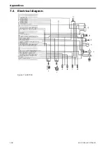
Page 108: ...Appendices 108 Ver 07 06 01 07 06 01 7 4 Electrical diagram Figure 7 8 307335...

