


vacon • 144
Parameters
Local contacts: https://www.danfoss.com/en/contact-us/contacts-list/
This parameter allow the under voltage controller to be switched out of operation. This may be use-
ful, for example, if the mains supply voltage varies more than -15% and the application will not tol-
erate this under voltage. In this case, the regulator controls the output frequency taking the supply
fluctuations into account.
NOTE!
This parameter will be automatically set during the identification run. It is recommended to
make the identification run, if possible. See parameter P3.1.2.4.
Stator voltage adjust
parameter is used only when
Permanent magnet synchronous motor (PMS
motor)
has been selected for parameter P3.1.2.2. This parameter has no affect if
Induction motor
has been selected. With an induction motor in use, the value has been internally forced to 100% and
it cannot be changed.
When the value of parameter P3.1.2.2 (Motor type) parameter is changed to
PMS Motor
, the param-
eters P3.1.4.2 (Field WeakngPnt) and P3.1.4.3 (Voltage at FWP) will be automatically extended up to
the limits of the drive's full output voltage, retaining the defined U/f-ratio. This internal extension is
done to avoid running the PMS motor in the field weakening area because the PMS motor nominal
voltage is typically much lower than the full output voltage capability of the drive.
PMS motor nominal voltage typically represents the motor’s back-EMF voltage at nominal frequen-
cy, but depending on the motor manufacturer, it may represent e.g. the stator voltage at nominal
load.
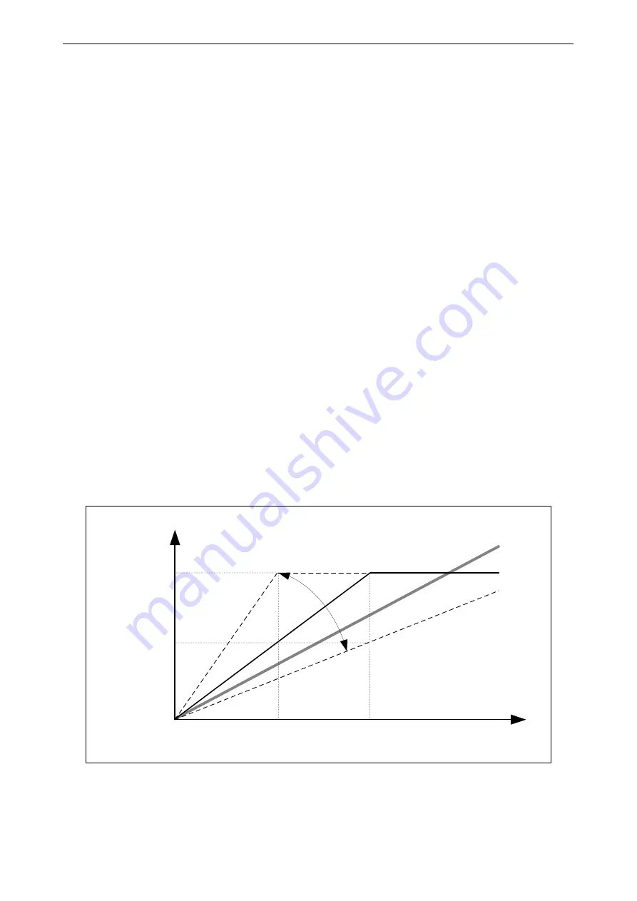
This parameter gives an easy way to adjust the drive’s U/f curve near to the motor’s back-EMF curve
without needing to change several U/f curve parameters. The StatorVoltAdjust parameter defines
the drive’s output voltage in percent of the motor’s nominal voltage at the motor’s nominal frequen-
cy.
The U/f curve of the drive is typically tuned slightly above the back-EMF curve of the motor. The mo-
tor current increases the more the drive’s U/f-curve differs from the motor’s back-EMF -curve.
Figure 41. Principle of Stator voltage adjustment
f
U
(50..200 %)
20
0
%
10
0
%
50
%
-
9208.emf
Field
Weakening
Point
Field Weakening
Point Voltage
Motor Nominal
Voltage
Motor Nominal
Frequency
Stator Voltage Adjust
ba
ck
EM
F


