ENGLISH
- 46 -
9.6 - PHOTOCELLS
Photocells can be activated in two ways:
1.
Only during closing
: in which case the passage in front of
the beam would cause the immediate reopening.
2.
During the opening and closing
: in which case the
interruption of the beam causes the immediate arrest. When
the beam is freed, a complete reopening of the barrier occurs.
m
ATTENTION: install the photocells to cover the entire
opening / closing surface of the boom.
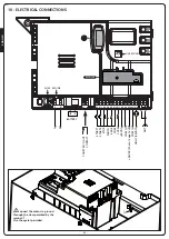
The control unit PD16 provides 24VDC power supply for the
photocells and it can test their performance before beginning the
opening of the boom. An electronic fuse that shuts down the
power supply in case of an overload protects the power supply
terminals of the photocells.
• Connect the feeder cables of the photocells transmitter
between terminals
M10 (+)
and
M9 (-)
of the control unit.
• Connect the feeder cables of the photocells receiver between
terminals
M8 (+)
and
M9 (-)
of the control unit.
• Connect the Common and the N.C. (Normally Closed) contact
of the photocells receiver on terminals
M4 (PHOTO)
and
M6 (COM)
of the control unit. Use the exits with normally
closed contact.
m
ATTENTION
:
• if more photocells copies of the same kind are to be installed,
their outputs must be connected in series.
• if reflection photocells are to be installed, the power supply
must be connected to terminals
G3 (+)
and
G2 (-)
of the
control unit to carry out the functional test.
• The photocells are not powered when the control unit
switches to ENERGY SAVING mode
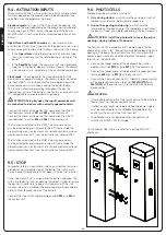
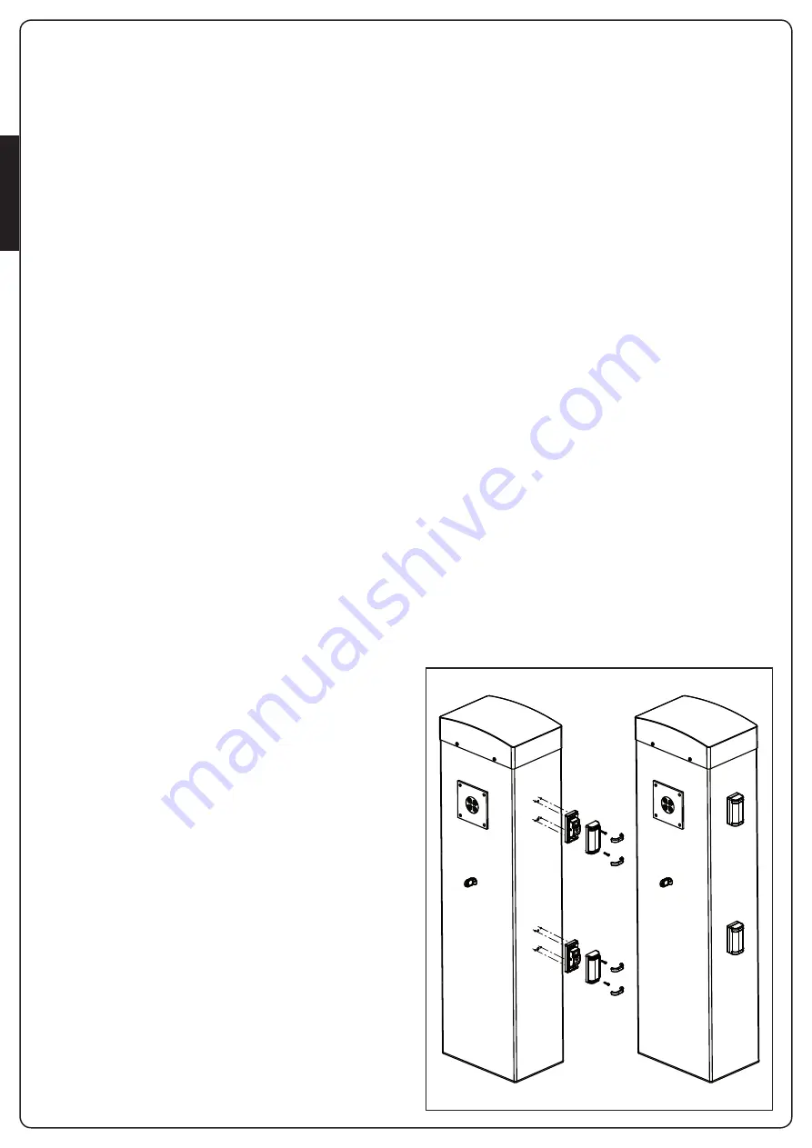
On the cabinet sides there are holes for installing SENSIVA
photocells:
9.4 - ACTIVATION INPUTS
The control unit PD16 has two activation inputs available, whose
functions depend on the programmed mode of operation (See
voice
Strt
on the programming menu):
Standard mode
: first input (START1) controls the opening, the
closing and the arrest depending on the programming mode set.
The second input (START2) causes the opening of the barrier
MASTER when it is activated the synchronized operation of two
barriers.
Open/Close and Dead Man mode
: an input command on
push-button START1 always commands the opening and an input
command on push-button START2 always commands the closing.
• In the
Open/Close
mode the command is of impulsive type,
that is, an impulse causes the total opening or closing of the
barrier.
• In the
Dead Man
mode, the command is of the monostable
type, that is the barrier opens or closes as long as the contact
is closed and arrests immediately if the contact becomes open.
Clock mode
: it is analogous to the standard mode, but the
barrier remains opened as long as the contact remains closed on
the input START1; when the contact comes opened begins the
pause countdown, which upon expiring the barrier recloses.
This function allows programming throughout the day the
opening hour cycles of the barrier, using for this an external timer.
It is indispensable to enable automatic reclosing.
m
ATTENTION: in all modes, the input commands must
be connected to devices with normally opened contacts.
Connect the cables of the device that commands the START1
input between terminals
M1
and
M6
of the control unit.
Connect the cables of the device that commands the START2
input between terminals
M2
and
M6
of the control unit.
The function associated to the START1 input command can
also be activated by pressing push-button
h
from outside the
programming menu, or by means of a remote control command
memorized on channel 1 (see the instructions of receiver MR).
The function associated to the START2 input command can
also be activated by pressing push-button
i
from outside the
programming menu, or by means of a remote control command
memorized on channel 2 (see the instructions of receiver MR).
9.5 - STOP
For greater safety it is possible to install a push-button that when
pressed causes immediate stop of the barrier. The switch must
have a normally closed contact that opens in case of set in action.
If the stop switch is set in action while the barrier is opened, the
automatic reclosing function becomes disabled; in order to reclose
the barrier it is necessary to give a start command (if the start
function in pause is disabled, it becomes temporarily reenabled in
order to allow the lock release of the barrier).
Connect the stop switch cables between cables
M3
and
M6
of
the control unit.
Summary of Contents for NIUBA-24V
Page 2: ...1153 mm 320 mm 287 mm 218 mm 897 mm 1168 mm 374 mm 239 mm 319 mm 897 mm ...
Page 7: ...ITALIANO 5 NIUBA4 NIUBA6 ...
Page 11: ...ITALIANO 9 FIG 3 FIG 4 ...
Page 13: ...ITALIANO 11 A D E C F F G E A B D C O N M ...
Page 31: ...ITALIANO 29 ...
Page 34: ...ITALIANO 32 ...
Page 39: ...ENGLISH 37 NIUBA4 NIUBA6 ...
Page 43: ...ENGLISH 41 FIG 3 FIG 4 ...
Page 45: ...ENGLISH 43 A D E C F F G E A B D C O N M ...
Page 63: ...ENGLISH 61 ...
Page 66: ...ENGLISH 64 ...
Page 71: ...FRANÇAIS 69 NIUBA4 NIUBA6 ...
Page 75: ...FRANÇAIS 73 FIG 3 FIG 4 ...
Page 77: ...FRANÇAIS 75 A D E C F F G E A B D C O N M ...
Page 95: ...FRANÇAIS 93 ...
Page 98: ...FRANÇAIS 96 ...
Page 103: ...ESPAÑOL 101 NIUBA4 NIUBA6 ...
Page 107: ...ESPAÑOL 105 FIG 3 FIG 4 ...
Page 109: ...ESPAÑOL 107 A D E C F F G E A B D C O N M ...
Page 127: ...ESPAÑOL 125 ...
Page 130: ...ESPAÑOL 128 ...
Page 131: ......


