ENGLISH
- 45 -
9 - CONTROL UNIT
PD16 is provided with a display that, not only makes
programming simple, but also allows a continuous monitoring of
the input statuses; in addition, thanks to a menu structure, the
working schedule and the operation logic can be set easily.
In compliance with the European standards concerning electrical
safety and electromagnetic compatibility (EN 60335-1,
EN 50081-1 and EN 50082-1) it has been equipped with the low
voltage circuit total electric insulation (motors included) from the
network voltage.
Other characteristics:
• Power supply protected from short circuits within the
controller, on the motors and on the connected accessories.
• Adjustment of the power by partializing the current.
• Detecting obstacles by monitoring the current on the motors
(current sensing probe and encoder)
• Automatic learning of the limit switch position
• Tests for safety devices (photocells, safety ribbons and mosfet)
before each opening.
• Deactivation of safety inputs through the configuration menu:
no jumper is required for terminals concerning safety devices
that have not been installed, yet. You will only need to disable
this function from its relevant menu.
• The device can operate without mains power, by using the
optional battery pack (code 161212).
• Low voltage output that can be used for a signal light or a
24V flashing light.
• Auxiliary relay with programmable logic for courtesy light,
flashing light or other use.
• ENERGY SAVING FUNCTION
• Synchronized operation of two motors using the SYNCRO
optional module
m
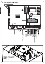
WARNING: Installation of control unit and safety
devices must be carried out with power disconnected
9.1 - POWER SUPPLY
The control unit must be fed by a 230V-50Hz or 120V-60Hz
electric line, protected by a differential magnetothermal switch
complying with the law provisions in force.
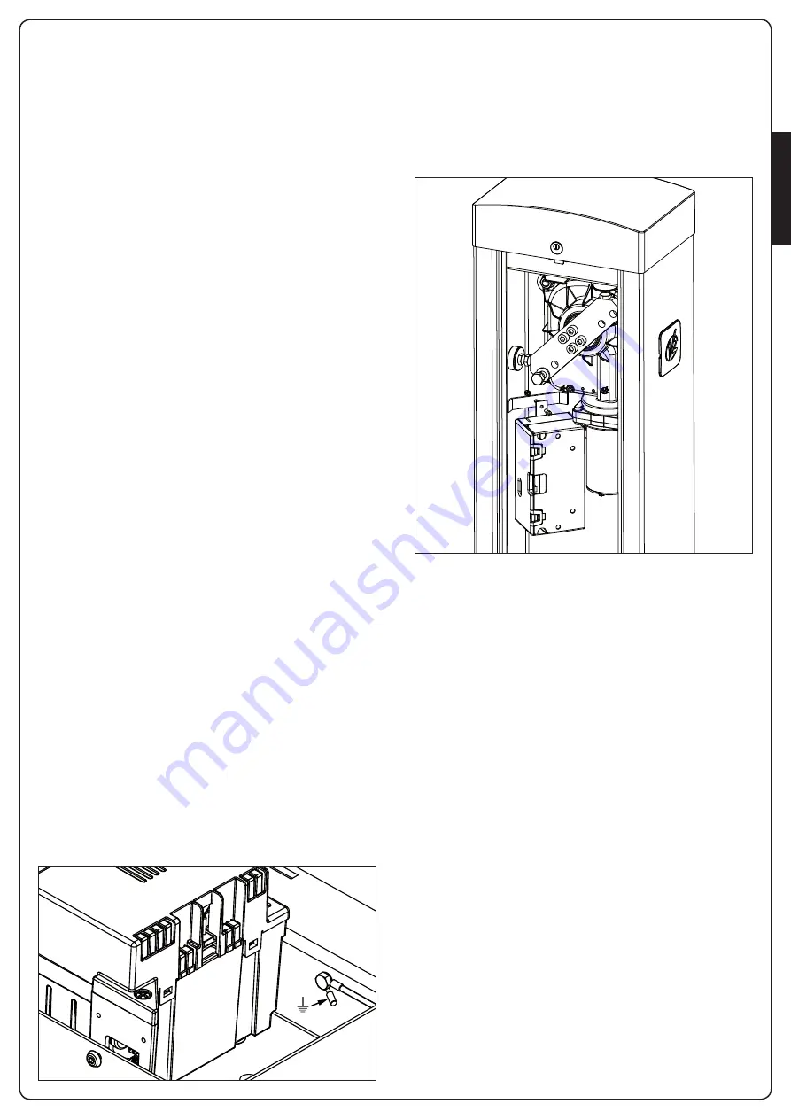
Connect the power supply wires to terminals
L
and
N
on the
board located next to the transformer.
Connect the earth cable to terminal
W
9.2 - BATTERY POWER SUPPLY
In the case of an electricity black-out, the device may be powered
using a battery pack (accessory code 161212).
The battery pack should be housed in the specific seating, as
shown in the figure.
Connect the battery pack connecter to the BATTERY terminals on
the control unit.
9.3 - ECO-LOGIC POWER SUPPLY
The barrier can be powered by the solar power system
ECO-LOGIC.
Install the ECO-LOGIC system following the instructions included
with the product.
Connect the output of the battery box (black connector) on
BATTERY fastons of the control unit.
NOTE: it is recommended the batteries be pre-charged prior
to installation
m
WARNING: activate the Energy Saving function
m
WARNING: If you use the ECO-LOGIC to power the
barrier, do not connect the power supply on terminals N
and L
Summary of Contents for NIUBA-24V
Page 2: ...1153 mm 320 mm 287 mm 218 mm 897 mm 1168 mm 374 mm 239 mm 319 mm 897 mm ...
Page 7: ...ITALIANO 5 NIUBA4 NIUBA6 ...
Page 11: ...ITALIANO 9 FIG 3 FIG 4 ...
Page 13: ...ITALIANO 11 A D E C F F G E A B D C O N M ...
Page 31: ...ITALIANO 29 ...
Page 34: ...ITALIANO 32 ...
Page 39: ...ENGLISH 37 NIUBA4 NIUBA6 ...
Page 43: ...ENGLISH 41 FIG 3 FIG 4 ...
Page 45: ...ENGLISH 43 A D E C F F G E A B D C O N M ...
Page 63: ...ENGLISH 61 ...
Page 66: ...ENGLISH 64 ...
Page 71: ...FRANÇAIS 69 NIUBA4 NIUBA6 ...
Page 75: ...FRANÇAIS 73 FIG 3 FIG 4 ...
Page 77: ...FRANÇAIS 75 A D E C F F G E A B D C O N M ...
Page 95: ...FRANÇAIS 93 ...
Page 98: ...FRANÇAIS 96 ...
Page 103: ...ESPAÑOL 101 NIUBA4 NIUBA6 ...
Page 107: ...ESPAÑOL 105 FIG 3 FIG 4 ...
Page 109: ...ESPAÑOL 107 A D E C F F G E A B D C O N M ...
Page 127: ...ESPAÑOL 125 ...
Page 130: ...ESPAÑOL 128 ...
Page 131: ......


