M3000
Installation Manual
106
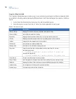
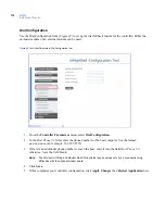
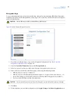
Using the Other Info field
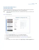
The Controller Information page provides access to several status reports based on uClinux commands which
are available for checking and monitoring the PXNplus board. Call Technical Support for assistance with these
reports.
1. In the
Other Info
field, click the down arrow for a list of available reports.
2. Select the report you want. See
Table 34
below for a brief explanation of each report.
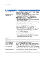
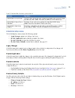
Table 34. Controller Info reports
Report
Description
Memory Usage
Displays the amount of memory available, both used and free.
Process Status
Lists which processes are running.
Board Info
Displays hardware related information, such as boot and board version.
OS Info
Displays information related to the Linux operating system on the controller.
Uptime
Indicates the time elapsed since the last reboot.
DB File Info
Lists persistence-related database files.
Message Info
Lists data on the controller’s message queues.
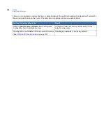
Ping Host
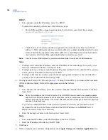
Pings the host from the controller (based on the current host IP or name).
Successful ping result:
2 packets transmitted, 2 packets received, 0% packet loss
Unsuccessful ping result:
2 packets transmitted, 0 packets received, 100% packet loss
Check Route
Checks route information from the controller.
Thread Status
Lists the application firmware components and whether they are currently running
DMA Info
Displays the status of the direct memory access (DMA) input/output (IO) interface.
Update history
List all updates to the firmware for selected controller.
Runtime Logs
Provides daily critical runtime information.
Summary of Contents for M3000
Page 1: ...M3000 Installation Manual P N 460630001H 15JUNE11 ...
Page 10: ...M3000 Installation Manual x ...
Page 39: ...Chapter 3 Power Communications board 29 Figure 11 Wiring modem to M3000 M 5 or serial printer ...
Page 47: ...Chapter 4 PXNplus CPU board 37 Board layout Figure 16 PXNplus CPU board layout ...
Page 58: ...M3000 Installation Manual 48 Board layout Figure 17 2RP reader board layout ...
Page 68: ...M3000 Installation Manual 58 Figure 24 Wiring 2RP door strike external relay ...
Page 72: ...M3000 Installation Manual 62 Board layout Figure 27 2SRP supervised reader board layout ...
Page 82: ...M3000 Installation Manual 72 Figure 19 Wiring 2SRP door alarm contact and exit request ...
Page 84: ...M3000 Installation Manual 74 Figure 21 Wiring 2SRP door strike external relay ...
Page 89: ...Chapter 5 Reader processing boards 79 Board layout Figure 24 8RP reader board layout ...
Page 92: ...M3000 Installation Manual 82 Figure 26 Wiring 8RP to F 2F or Supervised F 2F Readers ...
Page 94: ...M3000 Installation Manual 84 ...
Page 97: ...Chapter 6 Optional DI and DO boards 87 Figure 31 20DI board layout ...
Page 99: ...Chapter 6 Optional DI and DO boards 89 Figure 32 Wiring DI point ...
Page 101: ...Chapter 6 Optional DI and DO boards 91 Figure 33 16DO board layout ...
Page 102: ...M3000 Installation Manual 92 Figure 34 16DOR board layout ...
Page 104: ...M3000 Installation Manual 94 Figure 36 Wiring output device to 16DOR board ...
Page 152: ...M3000 Installation Manual 142 ...
Page 156: ...M5 controller Installation Manual 146 Figure 76 Installing ferrite ...
Page 160: ...M5 controller Installation Manual 150 ...
Page 172: ...M3000 Installation Manual 162 ...


