


Chapter 8
Controller firmware tools
135
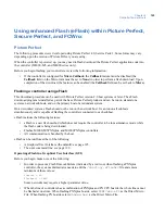
Result:
The configuration for the controller is retrieved and the
Micro Parameter Configuration
window displays (
Figure 62
).
-
The
Micro Parameter - Direct/Dialup
tab provides options for changing the connection type
of the controller and its
Address
,
Idle Time
, and
DI res tolerance
.
Figure 62.Micro Parameter - Direct/Dialup tab
-
The
Micro Parameter - Badge Format
tab provides options for selecting a magnetic stripe or
Wiegand format.
Figure 63.Micro Parameter - Badge Format tab
-
The
Micro Parameter - Networking
tab is read only. Use the Integrated Configuration Tool
to update this information. See
Using the Integrated Configuration Tool
on page 98 for details.
7. Make your changes and click
OK
.
Summary of Contents for M3000
Page 1: ...M3000 Installation Manual P N 460630001H 15JUNE11 ...
Page 10: ...M3000 Installation Manual x ...
Page 39: ...Chapter 3 Power Communications board 29 Figure 11 Wiring modem to M3000 M 5 or serial printer ...
Page 47: ...Chapter 4 PXNplus CPU board 37 Board layout Figure 16 PXNplus CPU board layout ...
Page 58: ...M3000 Installation Manual 48 Board layout Figure 17 2RP reader board layout ...
Page 68: ...M3000 Installation Manual 58 Figure 24 Wiring 2RP door strike external relay ...
Page 72: ...M3000 Installation Manual 62 Board layout Figure 27 2SRP supervised reader board layout ...
Page 82: ...M3000 Installation Manual 72 Figure 19 Wiring 2SRP door alarm contact and exit request ...
Page 84: ...M3000 Installation Manual 74 Figure 21 Wiring 2SRP door strike external relay ...
Page 89: ...Chapter 5 Reader processing boards 79 Board layout Figure 24 8RP reader board layout ...
Page 92: ...M3000 Installation Manual 82 Figure 26 Wiring 8RP to F 2F or Supervised F 2F Readers ...
Page 94: ...M3000 Installation Manual 84 ...
Page 97: ...Chapter 6 Optional DI and DO boards 87 Figure 31 20DI board layout ...
Page 99: ...Chapter 6 Optional DI and DO boards 89 Figure 32 Wiring DI point ...
Page 101: ...Chapter 6 Optional DI and DO boards 91 Figure 33 16DO board layout ...
Page 102: ...M3000 Installation Manual 92 Figure 34 16DOR board layout ...
Page 104: ...M3000 Installation Manual 94 Figure 36 Wiring output device to 16DOR board ...
Page 152: ...M3000 Installation Manual 142 ...
Page 156: ...M5 controller Installation Manual 146 Figure 76 Installing ferrite ...
Page 160: ...M5 controller Installation Manual 150 ...
Page 172: ...M3000 Installation Manual 162 ...