


M3000
Installation Manual
64
= OFF
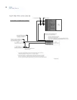
Note:
The boards MUST be numbered consecutively. This means that the first reader board must be set to Address
1, the second reader board must be set to Address 2, and so on. If they are not, the supervised DI points will
not work correctly.
Wiegand -
2802
ON
ON
ON
2804
3600
2700
ON
ON
2801
32 bit Motorola Indala
75 bit PIV
2800
ON
ON
ON
35/37 bit Hughes
26 bit
ON
ON
ON
55 bit
34 bit CardKey
35 bit Hughes
4002
2500
ON
ON
ON
ON
2804
3400
3703
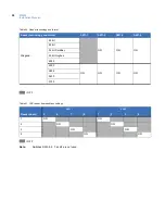
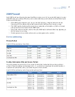
Table 28. Reader board (2SRP) address settings
Reader board
SW3-
SW4-
5
6
7
8
1
2
3
4
1
ON
ON
2
ON
ON
3
ON
ON
4
ON
ON
Table 27. Reader technology and format (continued)
Reader technology and format
SW3-1
SW3-2
SW3-3
SW3-4
1. Secure Perfect uses this switch setting as Custom Wiegand.
2. Only the PXNplus CPU board supports the 64 bit BCD badge format. If using the 64 bit BCD badge format, see “Wiring readers” on
page 67 for special wiring instructions.
= OFF
Summary of Contents for M3000
Page 1: ...M3000 Installation Manual P N 460630001H 15JUNE11 ...
Page 10: ...M3000 Installation Manual x ...
Page 39: ...Chapter 3 Power Communications board 29 Figure 11 Wiring modem to M3000 M 5 or serial printer ...
Page 47: ...Chapter 4 PXNplus CPU board 37 Board layout Figure 16 PXNplus CPU board layout ...
Page 58: ...M3000 Installation Manual 48 Board layout Figure 17 2RP reader board layout ...
Page 68: ...M3000 Installation Manual 58 Figure 24 Wiring 2RP door strike external relay ...
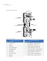
Page 72: ...M3000 Installation Manual 62 Board layout Figure 27 2SRP supervised reader board layout ...
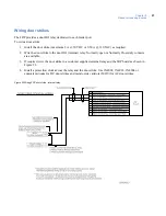
Page 82: ...M3000 Installation Manual 72 Figure 19 Wiring 2SRP door alarm contact and exit request ...
Page 84: ...M3000 Installation Manual 74 Figure 21 Wiring 2SRP door strike external relay ...
Page 89: ...Chapter 5 Reader processing boards 79 Board layout Figure 24 8RP reader board layout ...
Page 92: ...M3000 Installation Manual 82 Figure 26 Wiring 8RP to F 2F or Supervised F 2F Readers ...
Page 94: ...M3000 Installation Manual 84 ...
Page 97: ...Chapter 6 Optional DI and DO boards 87 Figure 31 20DI board layout ...
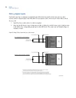
Page 99: ...Chapter 6 Optional DI and DO boards 89 Figure 32 Wiring DI point ...
Page 101: ...Chapter 6 Optional DI and DO boards 91 Figure 33 16DO board layout ...
Page 102: ...M3000 Installation Manual 92 Figure 34 16DOR board layout ...
Page 104: ...M3000 Installation Manual 94 Figure 36 Wiring output device to 16DOR board ...
Page 152: ...M3000 Installation Manual 142 ...
Page 156: ...M5 controller Installation Manual 146 Figure 76 Installing ferrite ...
Page 160: ...M5 controller Installation Manual 150 ...
Page 172: ...M3000 Installation Manual 162 ...