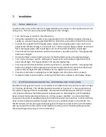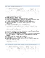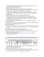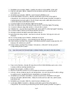
Page 22
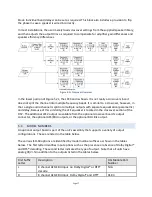
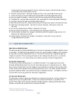
7.3 EIGHT CHANNEL ANALOG OUTPUT
1.
Power entry Module – Accepts IEC-‐type line cord from 100-‐240VAC power source. Also
contains a 500mA Slo-‐Blow 5x20mm fuse.
2.
Bypass Power Supply – 12VDC at 1.25A.
3.
RS-‐232 on a DE9F connector for communications with GUI or automation.
4.
SD Card – Stores a backup copy of unit configuration. Can also be used to transfer settings
to another unit or read by the GUI to download to a connected unit.
5.
AES/EBU input connector (RJ45) – parallel connections to the DB25F to the right.
6.
Ethernet connector (RJ45) – Network communications with GUI, web browsers,
automation, etc.
7.
AES/EBU input connector (DB25F) – Eight channels, DMA8 pin out.
8.
Automation DB25F Connector – Receives automation pulses from other system
components. Ten Control input lines with ground and 5V power provided to support a
standard pulse to ground system. The 5V output can power a JSDV-‐80 remote volume
control that pulses control lines 9 and 10.
9.
COAX -‐ RCA connector for S/PDIF PCM or optional DTS® and Dolby Digital® decoding.
10.
TOSLINK Port – Optical Fiber input (PCM) with optional DTS® and Dolby Digital® decoding.
11.
Hearing Impaired/VisuallyImpaired-‐Narrative outputs.
12.
Eight Channel Analog output provides six fixed outputs (L, C, R, LFE, Ls, Rs) and two that can
be set up as either Lc/Rc or Lrs/Rrs. Other output configurations, such as drive in, are
supported.
13.
Six Channel Analog Input on DB25F – Balanced line inputs.
14.
Non Sync (N/S) connectors – L and R analog inputs, RCA type connectors.
15.
Public Address and Real Time Analyzer microphone phantom power supply selector, 12V
balanced, 9V unbalanced, and off.
16.
Public Address and Real Time Analyzer microphone – XLR and ¼” stereo jack with
configurable phantom power.
7.4
AES/EBU OUTPUT REAR PANEL CONNECTIONS (JSD-‐60LS OR JSD-‐60DS)


