


Page 16
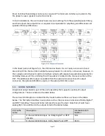
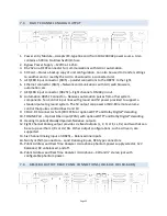
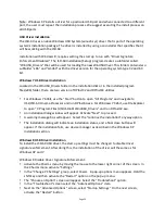
Figure 5.2b Audio Sources Overview including optional DI-‐84.
Each output, including HI and VI-‐N, has a mixer with eight digital and six analog inputs. The
input source and decode options determine the active sources for the mixer.
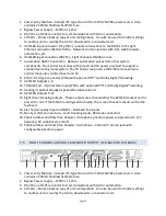
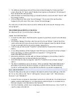
Simplified Crossover Block Diagram
The following Figure 5.2c shows the details of the crossovers. The audio is split into high band
and low band components with high pass filter #4 and low pass filter #0. These are both 4th
order Linkwitz-‐Riley filters. They are followed by a series of parametric filters. The high band
includes a pair of shelving filters (#7 and #8) to compensate for the high frequency
characteristics of the high frequency horn and the screen. Each band ends up with a delay


