49
2.
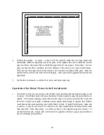
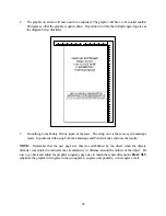
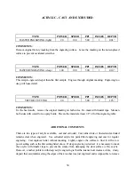
The graphic on screen will now need to be adjusted. The graphic will have to be rotated another
90 degrees so that the graphic is upside down. Reposition it within the defined engraving area as
the diagram below illustrates.
3.
Do nothing to the Rotary Fixture inside of the laser. The setup on it is the same as in Landscape
mode. Experiment with using both the Landscape and Portrait modes and note the results.
NOTE:
Remember that the new page size that was established by the driver when the objects
diameter was entered in indicates the circumference or distance around the outside of the object. Be
sure to go back and adjust the graphics programs page size to match these new dimensions
EXACTLY
otherwise the graphic will engrave in the wrong place, engrave only partially, or not engrave at all.
Summary of Contents for ULS-25
Page 3: ...3 APPENDIX E SOFTWARE ANOMALIES E...
Page 14: ...14 Sample Exhaust System Layouts...
Page 62: ...62...
Page 82: ...A APPENDIX A WARRANTY...


