32
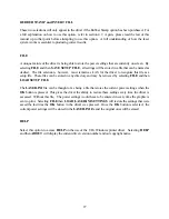
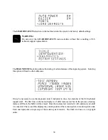
The
# OF COPIES
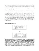
feature on the second line indicates the number of times the current file has been
used since it was loaded into the buffer (the system keeps a running count of the number of times each
file in the buffer has been processed). The second line also contains a timer to time files as they are run
(this is useful for costing jobs). The timer will pause when the
PAUSE
key is pressed and starts up
again when cutting or engraving has been resumed.
The last two lines show the power setting last used by the laser system.
BLACK
indicates the current
power setting color used for all of the portions of the computer artwork which are colored black,
SPEED
indicates the speed of the motion system,
POWER
indicates the power output of the laser
and the
PPI
setting indicates the laser’s pulse rate (in this case 500 laser pulses per inch). The
OPERATIONS DISPLAY
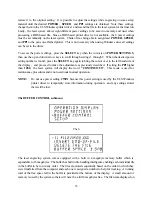
mode is the part of the menu system that is used most often. In this mode,
the file name will be displayed as well as the current power setting that the laser system is processing.
When the laser system is first powered on and this submenu is selected, there will be an initial power
setting displayed. Even after the first file is downloaded and the name of the file appears on the display,
the power setting will still be unchanged. Please ignore these settings. Only until the file is run will the
display show the correct power setting that was entered in the ULS Windows printer driver when the
file was sent to print.
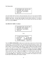
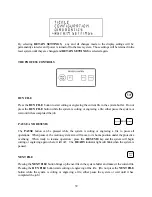
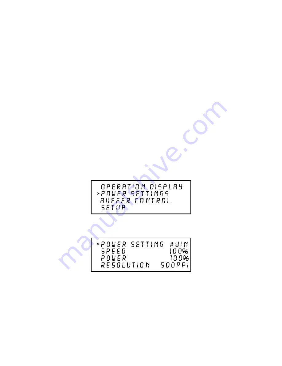
The POWER SETTINGS submenu
Then
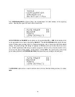
This submenu serves several purposes. The first purpose is to display the current power settings the
laser system is using while it is running a job. This is very similar to the
OPERATIONS
DISPLAY
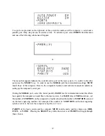
submenu except that the name of the file running is not shown. Secondly, it is possible to change these
settings while the laser system is running which is very useful for testing purposes. To adjust these
settings, press the up or down arrow key until the cursor is on the desired selection. Press the
SELECT
key which moves the cursor to the right and then use the arrow keys to increase or decrease
the values. Pressing the
SELECT
key again will accept the change and pressing the
ESCAPE
key will
Summary of Contents for ULS-25
Page 3: ...3 APPENDIX E SOFTWARE ANOMALIES E...
Page 14: ...14 Sample Exhaust System Layouts...
Page 62: ...62...
Page 82: ...A APPENDIX A WARRANTY...

