background image

© 2023 United States Stove Company

9

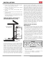
E.  Minimum 2-foot (0.61m) clearance above any grass, 

plants, or other combustible materials.

F.  Minimum 3-foot (0.91m) clearance from an forced 

air intake of any appliance.

G.  Minimum 2-foot (0.61m) clearance below eves or 

overhang.

H.  Minimum 1-foot (0.3m) clearance horizontally from 

combustible wall.

I.  Must be a minimum of 3 foot (0.91m) above the roof 

and 2 foot (0.61m) above the highest point or the roof 

within 10 feet (3.05m).

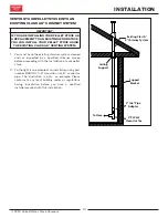
THROUGH THE WALL INSTALLATION 

(RECOMMENDED INSTALLATION)

TYPICAL THROUGH THE 

WALL INSTALLATION

To Stove

Canadian installations must conform to CAN/CSA-B365. 

To vent the unit through the wall, connect the pipe 

adapter to the exhaust motor adapter. If the exhaust 

adapter is at least 18” (457 mm) above ground level, a 

straight section of pellet vent pipe can be used through 

the wall. Your heater dealer should be able to provide 

you with a kit that will handle most of this installation, 

which will include a wall thimble that will allow the proper 

clearance through a combustible wall. Once outside the 

structure, a 3” (76 mm) clearance should be maintained 

from the outside wall and a clean out tee should be 

placed on the pipe with a 90-degree turn away from the 

house. At this point, a 3ft (0.91m) (minimum) section of 

pipe should be added with a horizontal cap, which would 

complete the installation. A support bracket should be 

placed just below the termination cap or one every 4ft 

(1.22m) to make the system more stable. If you live in an 

area that has heavy snowfall, it is recommended that the 

installation be taller than 3ft (0.91m) to get above the 

snowdrift line. This same installation can be used if your 

heater is below ground level by simply adding the clean-

out section and vertical pipe inside until ground level is 

reached. With this installation you have to be aware of the 

snowdrift line, dead grass, and leaves. We recommend 

a 3ft (0.91m) minimum vertical rise on the inside or 

outside of the house. The “through the wall” installation 

is the least expensive and simplest installation. Never 

terminate the end vent under a deck, in an alcove, under 

a window, or between two windows. We recommend 

Simpson Dura-Vent® or Metal-Fab® kits.

THROUGH THE ROOF/CEILING 

INSTALLATION

•  When venting the heater through the ceiling, the pipe 

is connected the same as through the wall, except the 

clean-out tee is always on the inside of the house, and a 

3” (76 mm) adapter is added before the clean-out tee. 

•  You must use the proper ceiling support flanges and 

roof flashing (supplied by the pipe manufacturer; follow 

the pipe manufacturer’s directions). It is important to 

note that if your vertical run of pipe is more than 12ft 

(3.7m), the pellet vent pipe size should be increased to 

4” (102 mm) in diameter. 

•  Do not exceed more than 4ft (1.22m) of pipe on a 

horizontal run and use as few elbows as possible. If 

an offset is required, it is better to install 45-degree 

elbows rather than 90-degree elbows.

WARNING:

YOU MAY WANT TO LOCATE ANY UTILITIES 

OR OBSTACLES INSIDE THE WALL BEFORE 

ATTEMPTING THIS INSTALL. MAKE SURE 

TO KEEP IN MIND YOUR UNIT’S CLEARANCE 

REQUIREMENTS.

1.  Mark the area and then cut the wall for vent 

installation if needed.

2.  Install the wall thimble as specified by the 

manufacturer (wall thimble sold separately).

3.  Install venting.

INSTALLATION

Summary of Contents for US5513-W

Page 1: ...IAPROPOSITION65WARNING This product can expose you to chemicals including carbon monoxide whichisknowntotheStateofCaliforniatocause cancer birth defects and or other reproductive harm For more informa...

Page 2: ...uel Burn Rate lowest setting 1 65 lbs hr 0 75 kg hr Pellet size may effect the actual rate of fuel feed and burn times Fuel feed rates may vary by as much as 20 Use PFI listed fuel for best results Bu...

Page 3: ...and_____________________________________________ If no Date of inspection of existing venting system ________________________________________________________________ COMMISSIONING Confirm Hearth Pad I...

Page 4: ...Pin Com Cable 2 Unpack the top mount controls and ensure that all wires are securely attached 3 Connect the factory installed 5 Pin Main Wiring Harness to the top right hand corner of the control pan...

Page 5: ...IS REQUIRED THIS UNIT MUST BE PLUGGED INTO A 110 120V 60 HZ GROUNDED ELECTRICAL OUTLET DO NOT USE AN ADAPTER PLUG OR SEVER THE GROUNDING PLUG DO NOT ROUTE THE ELECTRICAL CORD UNDERNEATH IN FRONT OF O...

Page 6: ...Canada Floor protector must comply with CAN ULC standards Must extend 18 458mm forward and 8 204mm beyond each side of unit A Back to Stove U S A 1 26 mm CAN 8 204 mm B Side to Stove U S A 6 153 mm CA...

Page 7: ...hassis of the mobile home transportable building with 8 GA copper wire using a serrated or star washer to penetrate paint or protective coating to ensure grounding Vent must be 3 or 4 inch PL Vent and...

Page 8: ...disassemble for cleaning and should be checked several times during the burning season Pellet vent pipe is not furnished with the unit and must be purchased separately PELLET VENT INSTALLATION The in...

Page 9: ...nstallation be taller than 3ft 0 91m to get above the snowdrift line This same installation can be used if your heater is below ground level by simply adding the clean out section and vertical pipe in...

Page 10: ...d or inspected by a qualified chimney sweep before proceeding with the installation of your pellet stove 2 To the right is an example of an installation using part number 860001 3 6 transition into 6...

Page 11: ...located on the front lower left hand corner of your heater ON OFF Pressing the ON button on the control panel will begin the start up sequence for the heater Fuel will begin to feed through the auger...

Page 12: ...educed performance Store your pellets in a dry place DO NOT store the fuel within the installation clearances of the unit or within the space required for refuelling and ash removal Doing so could res...

Page 13: ...3 4 will give you a higher heat output above medium and the damper should be open for these settings If the door is opened while the stove is in operation it must be closed within 30 seconds or the s...

Page 14: ...MES EXCEPT WHEN REFILLING DO NOT OVERFILL HOPPER TAMPER WARNING This wood heater has a manufacturer set minimum low burn rate that must not be altered It is against federal regulations to alter this s...

Page 15: ...e heat exchanger To access these clean outs you must remove both side panels The clean outs are secured to the firebox with 2 5 16 screws Remove the clean outs and vacuum out any accumulated ash This...

Page 16: ...ect the vent from the stove GLASS We recommend using a high quality glass cleaner Should a buildup of creosote or carbon accumulate you may wish to use 000 steel wool and water to clean the glass DO N...

Page 17: ...lowers annually Remove the exhaust blower from the exhaust duct and clean out the internal fan blades as part of your fall start up If you have indoor pets your power motors should be inspected monthl...

Page 18: ...he chimney venting for transportation of a transportable building The parts or materials to be employed for ember protectors and the minimum areas to be covered and their relation to the space heater...

Page 19: ...se the slide about 1 4 after your stove cools down Restart your stove If your display shows E1 again close the slide another 1 4 and restart The convection blower is overheating and tripping the inter...

Page 20: ...ombustion blower failure With the stove on check to see if the combustion blower is running If it is not you will need to check for power going to the combustion blower It should be a full current If...

Page 21: ...move the two bolts that hold the auger bracket to the auger tube The auger bracket will now be able to be removed form the auger tube Remove the two bolts on the side of the auger tube to remove the l...

Page 22: ...ating the unit be sure the hopper lid is closed so that the hopper safety switch will activate Check the wires leading from the hopper safety switch to the control panel and auger motor for secure con...

Page 23: ...The Home Possible Causes Possible Remedies Unplug stove first when possible There is a leak in the vent pipe system Inspect all vent pipe connections Make sure they are sealed with RTV silicone that...

Page 24: ...e caused a jam Loose wire or connector Check all wires and connectors that connector to the auger motor high limit switch and the Molex connector Bad control board If the fuse is good the wires and co...

Page 25: ...l Burnpot holes are blocked Remove the burnpot and thoroughly clean it Blockage in air intake pipe Visually inspect the air intake pipe that leads into the burnpot for foreign material Combustion blow...

Page 26: ...Microswitch 1 9 80631 PCBA Main 1 10 80709 Room Blower 1 11 88347 Gasket 2 12 80455 High Temp Snapdisc Air 1 13 80915 RTD Temperature Probe 1 Key Part Description Qty 14 80872 Exhaust Blower 1 15 808...

Page 27: ...2023 United States Stove Company 27 CORRECT WRONG Ensure the wires are connected to the bottom two prongs of the hopper switch as shown WIRING DIAGRAM...

Page 28: ..._____ Engineer Name _____________________________________ License No _________________________________________ Company ___________________________________________ Telephone No ________________________...

Page 29: ...____________________ Service de 07 Date ______________________ Nom de l ing nieur _________________________________ N de licence ______________________________________ Compagnie ______________________...

Page 30: ...2023 United States Stove Company 27 CORRECT FAUX Assurez vous que les fils sont connect s aux deux broches inf rieures de l interrupteur de la tr mie comme illustr SCH MA DE C BLAGE...

Page 31: ...de couvercle de nettoyage 2 7 80913 Circuit imprim Wi Fi 1 8 80491 Micro interrupteur 1 9 80631 PCBA principal 1 10 80709 Ventilateur de chambre 1 11 88347 Joint 2 12 80455 Air Snapdisc haute temp rat...

Page 32: ...rents bois ont des caract ristiques diff rentes lorsqu ils sont br l s L interrupteur de surchauffe se d clenche tout le temps Causes possibles Solutions possibles D branchez le po le avant toute chos...

Page 33: ...de l arbre de la tari re et essayez de le faire fonctionner Si le moteur tourne c est l arbre qui est coinc sur quelque chose Si le moteur ne tourne pas il est d fectueux Tari re bloqu e Commencez par...

Page 34: ...e tableau de commande n envoie pas de courant l allumeur V rifiez la tension qui arrive l allumeur lors du d marrage Ce doit tre la tension nominale Si la tension est inf rieure la valeur nominale v r...

Page 35: ...rm pour permettre l interrupteur de s curit de la tr mie de s activer V rifiez le branchement des fils qui partent de l interrupteur de s curit de la tr mie jusqu au tableau de commande et au moteur d...

Page 36: ...Retirez ensuite le moteur de la tari re en retirant la goupille de la tari re puis retirez les deux boulons qui fixent le support de tari re au tube de tari re Vous pouvez maintenant retirer le suppo...

Page 37: ...Panne du ventilateur de combustion Lorsque le po le est en marche v rifiez si le ventilateur de combustion est en fonctionnement Sinon v rifiez l alimentation lectrique du ventilateur de combustion Ce...

Page 38: ...nviron 1 4 po apr s que votre po le se soit refroidi Red marrez votre po le Si votre cran affiche nouveau E1 fermez la glissi re de 1 4 po et recommencez Le ventilateur de convection surchauffe et d c...

Page 39: ...ons du fabricant de la chemin e pour le d montage de la chemin e ventilation pour le transport d un b timent transportable Les pi ces ou mat riaux utiliser pour les protecteurs de braises et les surfa...

Page 40: ...agr La porte de cet appareil utilise un joint 5 8 po corde de diam tre MOTEURS DES VENTILATEURS Nettoyez tous les ans les orifices d a ration des moteurs des ventilateurs d vacuation et de distributio...

Page 41: ...accumulation de cr osote ou de carbone s accumule vous pouvez utiliser de la laine d acier et de l eau pour nettoyer le verre N UTILISEZ PAS de nettoyants abrasifs N effectuez PAS le nettoyage lorsqu...

Page 42: ...re po le Le po le devra s teindre et s teindre compl tement avant que vous puissiez red marrer le po le CHAMBRES INT RIEURES Graver Pot P riodiquement enlever et nettoyer le pot de combustion et la zo...

Page 43: ...REMPLISSAGE NE REMPLISSEZ PAS TROP LA TR MIE AVERTISSEMENT LA TR MIE ET LE COUVERCLE DU PO LE SONT CHAUDS PENDANT LE FONCTIONNEMENT VOUS DEVEZ TOUJOURS PROT GER VOS MAINS LORS DU REMPLISSAGE DU PO LE...

Page 44: ...ustion lev e votre po le doit tre r gl sur le r glage 5 avec le registre compl tement ouvert Pour obtenir une combustion moyenne votre po le doit tre r gl sur le r glage 1 avec le registre compl temen...

Page 45: ...Institute densit minimale de 40 lb par pied cube diam tre de 1 4 5 16 moins de 8 200 BTU lb humidit inf rieure 8 en poids cendres inf rieure 1 en poids et sel inf rieur 300 parties par million Les gra...

Page 46: ...nt en appuyant sur le s bouton s appropri s du tableau de commande qui se trouve dans le coin inf rieur gauche l avant de l appareil ALLUMAGE EXTINCTION L appui sur le bouton ON du tableau de commande...

Page 47: ...qualifi avant de proc der l installation de votre po le granul s 2 Vous trouverez ci dessous des exemples d installations utilisant le num ro de pi ce 860001 transition de 3 6 pouces vers un tuyau de...

Page 48: ...recommand que la sortie de l installation se trouve plus de 3 pi 0 91 m pour chapper la ligne de cong re Cette m me installation peut tre utilis e si le po le se trouve sous le niveau du sol en ajout...

Page 49: ...LLATION DE L EVACUATION POUR POELE A GRANULES L installation doit comprendre un T de nettoyage pour permettre la collecte des cendres volantes et le nettoyage p riodique du syst me d vacuation des fum...

Page 50: ...sorties ext rieures doivent tre r install es et refix es Une prise d air ext rieur est obligatoire pour l installation dans une maisons mobiles b timents portatif Consultez la section Admission d air...

Page 51: ...le conform ment aux d gagements indiqu s ci dessous Pour des raisons de s curit veuillez respecter les d gagements et restrictions d installation Toute r duction du jeu aux combustibles ne peut tre ef...

Page 52: ...LA COMBUSTION DU COMBUSTIBLE G N RE DU MONOXYDE DE CARBONE QUI PEUT S AV RER DANGEREUX POUR LA SANT EN L ABSENCE D UNE VENTILATION APPROPRI E ATTENTION UN D TECTEUR DE FUM E FONCTIONNEL DOIT TRE INST...

Page 53: ...ches 2 D ballez les commandes mont es sur le dessus et assurez vous que tous les fils sont solidement fix s 3 Connectez le faisceau de c blage principal 5 broches install en usine au coin sup rieur dr...

Page 54: ...n date d inspection du syst me de ventilation existant ___________________________________________________________________ MISE EN SERVICE Confirmer l installation du tapis de foyer conform ment aux i...

Page 55: ...l Agence am ricaine de protection de l environnement 2020 pour les appareils de chauffage au bois vendus apr s le 15 mai 2020 Dans des conditions de test sp cifiques il a t d montr que cet appareil d...

Page 56: ...AIS UTILISER CE PRODUIT SANS SURVEILLANCE MISE EN GARDE Veuillez lire l int gralit de ce manuel avant d installer ou d utiliser votre nouveau radiateur Le non respect des instructions peut entra ner d...

Reviews: