49
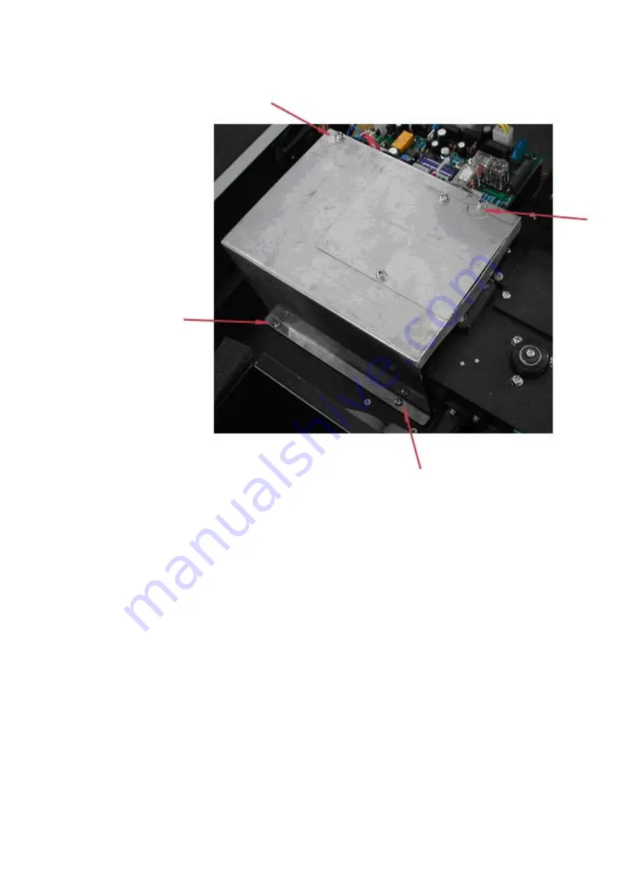
place the protective cover to the side. See Fig A4
Fig A4
6. Disconnecting the connector J7 on the PCB marked SST8.411.128.
Unscrew the screw that holds the lamp bracket to the instrument
base. Pull the entire lamp and lamp holder assembly out. See Fig
A5