EVK-IRIS-W10 - User guide
UBX-23007837 - R03
Hardware description
Page 17 of 43
C1-Public
3.3
Buttons
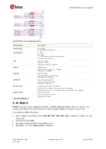
In addition to the
RESET
and
BOOT
buttons, EVK-IRIS-W1 has two more momentary push-
button switches. These switches are active-low or high and connect to ground or
+3V3
when
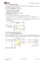
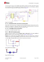
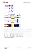
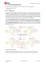
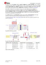
pressed. The buttons and the associated GPIO signals are shown in
and
Figure 17: EVK schematic - user buttons
describes the various user buttons and their relationship with the corresponding GPIO
signals.
Button function Reference designator GPIO
Function
SW_1
SW1
GPIO45
No predefined function (software controlled)
SW_2
SW2
GPIO51
No predefined function (software controlled)
BOOT
SW7
EXT-GNT
EXT-REQ
Pressing SW7 when R216 or R218 are installed starts the
bootloader in ISP or Serial mode respectively. See also
Automatic bootloader / Bootstrap
RESET
SW5
PDn
Resets the module, FTDI chip, and mikroBUS slots
Table 3: User button definitions
3.4
User LEDs
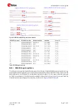
EVK-IRIS-W10 supports 16 LEDs:
•
Power status (
D10
): Indicates
3V3
on the board when lit (green) dependent on
SW6
•
MCU-LINK Power status (
D19
): Indicates
3V3
on MCU-LINK when lit (green), dependent on
SW6.
•
OTG (
D20
): Indicates OTG circuit is enabled lit (green).
•
OTG-Fault (
D2
): Indicates over current of the OTG circuit when lit (red).
•
MCU-LINK
(
LED1 - LED5
):
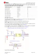
Indicate MCU-LINK connection status. See also
•
UART3 status (
D4–D9
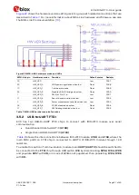
): Indicate UART3 signal status under GPIO control, as shown in
•
System status (
RGB1
): Powered by
+3V3
and turned on by pulling the associated GPIO low.
Associated GPIOs can be used as ADCs after disconnecting each LED by removing
resistors
R77–R79
, as shown in
RGB LED
Associated GPIO
Disable option
Red (pin1)
GPIO44
Remove R77 to disconnect
Green (pin2)
GPIO43
Remove R78 to disconnect
Blue (pin3)
GPIO42
Remove R79 to disconnect
Table 4: RGB LED-associated signals


