EVK-IRIS-W10 - User guide
UBX-23007837 - R03
Hardware description
Page 31 of 43
C1-Public
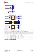
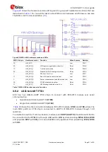
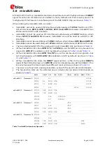
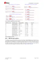
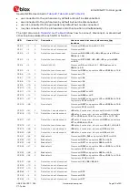
Figure 34: RMII demultiplexing resistors schematic
IRIS-W10 pin name
IRIS-W10 function
Related resistors
Interface
Pin on U1
N1
GPIO63/RMII-RXER
R285/R141
PHY-
RXER
Pin 20
J3
GPIO60/RMII-TXEN
R280
PHY-TXEN
Pin 23
M1
GPIO62RMII-CRSDV
R281/R140
PHY-CRSDV
Pin 18
L2
GPIO56/RMII-MDC
R263
PHY-DMC
Pin 12
L1
GPIO57/RMII-MDO
R265
PHY-MDIO
Pin 11
K2
GPIO59/RMII-TXD1
R276
PHY-TXD1
Pin 25
K1
GPIO58/RMII-TXD0
R275/R138
PHY-TXD0
Pin 24
J2
GPIO23/RMII-RXD1
R268/R139
PHY-RXD1
Pin 15
J1
GPIO22/RMII-RXD0
R272
PHY-RXD0
Pin 16
L4
GPIO55/RMII-INT
R111/R149
PHY-INT
Pin 21
F3
GPIO25/RMII-RXCLK
R279
PHY-RXCLK
Pin 9
M2
GPIO21/RMII-RESET
R210
PHY-RESET
Pin 32
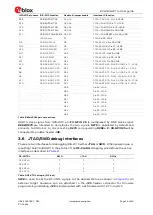
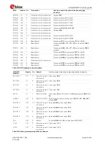
Table 19: RMII signals and pins
3.9.1
RMII Strap-in options
The strap-in pins are latched at the de-assertion of reset. the MAC RMII receive input pins may
drive high/low during power-up or reset, and consequently cause the PHY strap-in pins on the
RMII signals to be latched to unintended high/low states. In this case, external pull-ups
(4.7
kΩ) or pull
-downs (1.0
kΩ) should be added
to these PHY strap-in pins to ensure that the
intended values are strapped-in correctly, as shown in

