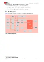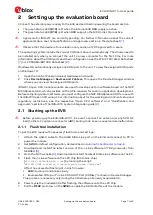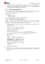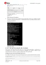
EVK-IRIS-W10 - User guide
UBX-23007837 - R03
Hardware description
Page 12 of 43
C1-Public
3.1.1
Powering the board
After applying power to one of the sources described in
, slide
SW6
shown in
to the ON position to power-on the EVK.
The input voltage
VBUS-OUT
is extended to:
•
3.3 V switching regulator input (
U11
)
•
3.3 V linear regulator input (
U20
)
•
USB 2.0 On-The-Go (OTG) circuit
•
VBUS-OUT
(5 V) connections on pin headers
•
mikroBUS slots 5 V positions
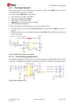
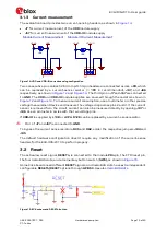
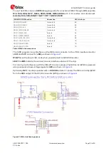
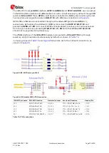
There are two options for the maximum current for the EVK, either:
•
Populate the 2.4 A power switch
U6
(MP5075GTF) and disconnect
R124,
as shown in
•
Limit the maximum current to 600 mA by populating
R124
with a 1206 0R 2A resistor and
disconnecting U6.
Figure 7: EVK-IRIS-W10 maximum current options
3.1.1.1
3.3 V switching regulator
(U11)
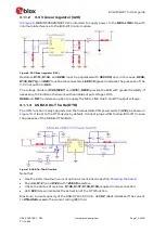
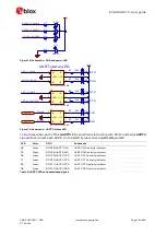
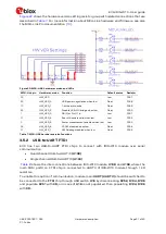
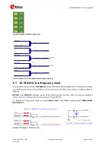
The EVB is populated with a fixed 3.3 V, 3 A switching regulator (TPS62132RGTR), as shown
in
. LED
D10
(green) indicates the presence of the 3.3 V output from the regulator
U11
.
Figure 8: Switching regulator (U11)


