EVK-IRIS-W10 - User guide
UBX-23007837 - R03
Hardware description
Page 15 of 43
C1-Public
3.1.3
Current measurement
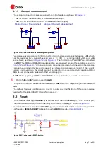
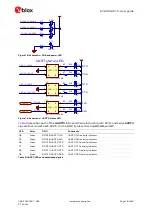
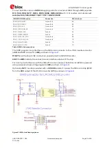
The evaluation board provides two current-sensing headers, as shown in
•
J7
for current measurement of the
VDD
module supply
•
J67
for current measurement of the
VDD-IO
module supply
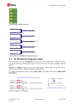
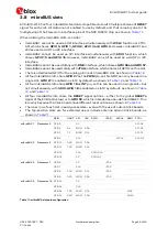
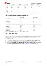
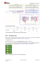
Figure 14: VDD and VDD-IO current sensing configuration
Two consecutive pins on Each 2.54
mm pitch 3-pin headers are connected across a
0R
, which
can be replaced by a current-sense resistor (
>
1R0
is recommended
),
J97,
and
J96
and
The third pin on
J7
and
J67
are connected
to
GND
. The
VDD
and
VDD-IO
module supplies are sourced through the resistors shown in
. To measure current consumption, use a multimeter or other precise
voltage measurement device and measure the voltage drop across pins 2 and 3. If the current
sensor is removed from the circuit, current can also be measured directly by opening
J97
or
J96
. Use an ammeter in series with the two voltage pins.
If
VDD-IO
is supplied by
+1V8
or
+VPA
,
R126
can be replaced by a current-sense resistor.
⚠
Pin 1 of
J7
and
J67
is connected to
GND
.
To bypass the current sense resistors,
R35
and
R62
, solder the respective jumpers
J94
and
J95.
The default hardware configuration doesn’t require any modification of the current-sense
headers for the EVK-IRIS-W10 to perform properly.
3.2
Reset
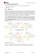
The active-low reset signal,
RESETn
, is connected to the module
PDn
pin, the FTDI reset pin,
the four mikroBUS slots, and a momentary button switch (
SW5),
Some Click boards need different
RESET
signals, and mikroBUS slots have extra independent
configurable
RESETn/RESET
options through
GPIO50
. See also
Figure 15: EVK schematic, RESETn button
+3V3
VDD
Module Current Measurement
+3V3
Module IO Current Measurement
1
2
3
J67
1
2
3
J7
VDD-IO
J95
J94


