Section 4. Configuration of the frequency converter
4.2.2. Control from the control panel
In order to control the drive from the control panel it is necessary to set up:
„Control place” A or B by par. 2.1
Parameter 2.2 (for A) or 2.3 (for B) should be set to “
133 Keyb ref.
”
Parameter 2.4 (for A) or 2.5 (for B) should be set to
„031 Keyboard St.”
Make sure that the constant speed selection is not active, i.e. the parameters:
2.30, 2.31, 2.32 should be set to
„000 Sw.Off”
.
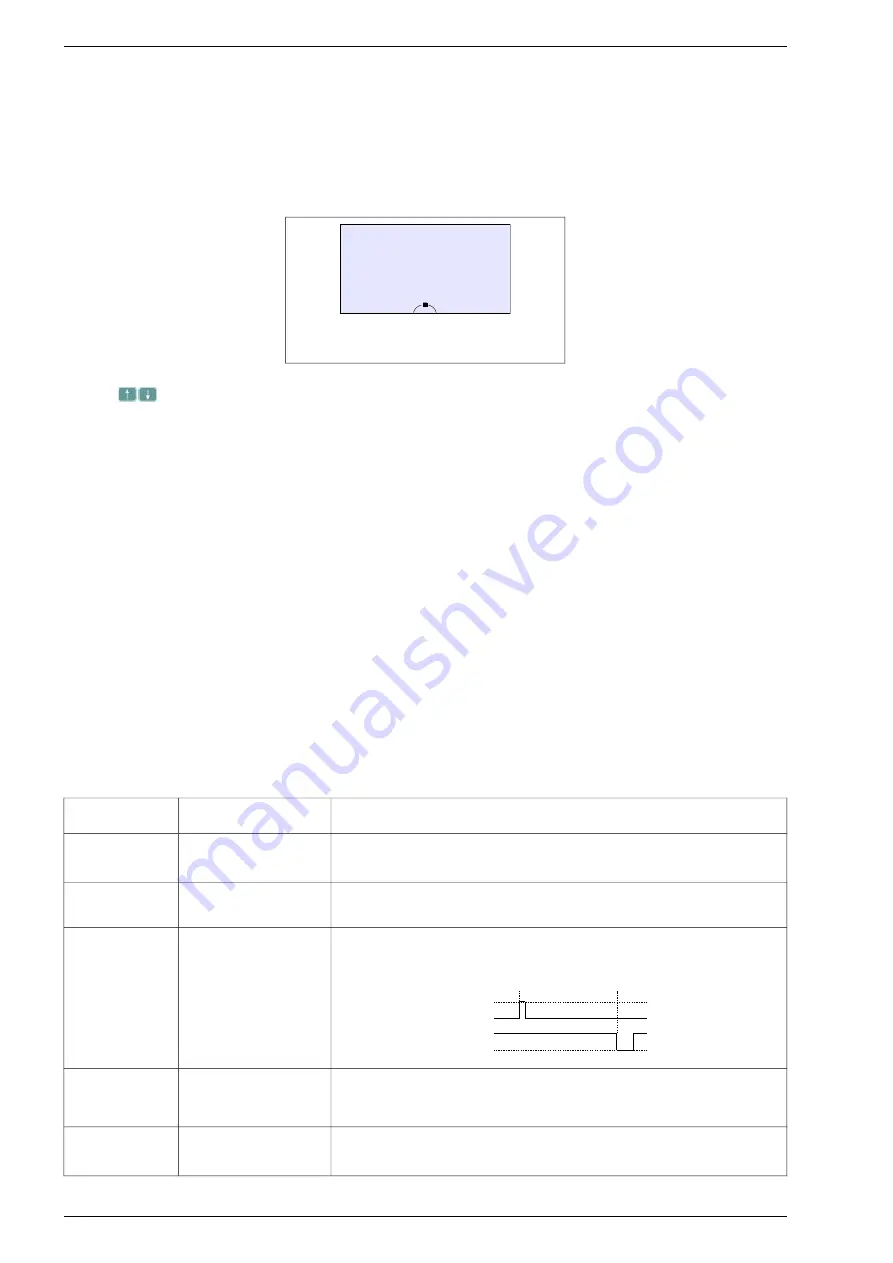
Fig. 4.3 - CONTROL STATE - referencing-unit
and START / STOP local (from the Control panel)
With this configuration, the changes in the system frequency value (or rotation speed in vector mode) are made using
the keys
. The motor is started and stopped from the Panel with the LEFT / RIGHT and STOP keys.
4.2.3. Control from terminal connections
In order to control the drive from the terminal block (e.g. START STOP through digital inputs DI and regulation
of rotation speed using a potentiometer) it is necessary to:
In order to control the drive from terminal connections form “control place B” (control place B is default for
remote control, control place A can also be used), e.g. START / STOP through digital inputs DI and regulation of rotation
speed using a potentiometer, it is necessary to:
Set up the „control place” A or B by parameter 2.1
(control place B is default for remote control and it is not recommended to modify the existing A control place,
which is assigned to the Control Panel by default).
Define the signal source of the converter output frequency reference by par. 2.2 (“control place” A) or par. 2.3
(“control place” B)
:
–
“134 In.A0”
for an analog input AI0
–
“135 In.A1”
for an analog input AI1
–
“136 In.A2”
for an analog input AI2
Set up the source of START/STOP signal by par. 2.4 (“control place” A) or 2.5 (“control place” B) to
“
030 Dig.Inp. St”
Make sure that the constant speed selection is not active, i.e. the parameters:
2.30, 2.31, 2.32 should be set to
„000 Sw.Off”
.
set up the parameter
2.8 "Remote start”
- it defines functions of control digital inputs as at the tab. 4.1.
Table 4.1 - possible configuration variants of remote start (START)
Value of par. 2.8
„Remote start”
Notation
Function
0
DI1 = START/STOP
DI2 = DIRECTION
Voltage feeding into digital input DI1 results in the drive start, while voltage removal
– in the drive stop. The condition of a digital input DI2 defines determines the
change of the motor rotation direction.
1
DI1 = START RIGHT
DI2 = START LEFT
Voltage feeding into digital input DI1 results in the start of motor. Voltage feeding
into digital input DI2 results in the motor start in opposite direction.
2
DI1 = PULSE START
DI2 = PULSE STOP
If a voltage pulse is applied to input 1 at high input 2, the motor will start. Removing
the voltage from Input 2 will stop the motor. The direction of rotation is determined
only by the reference sign.
STOP
START
DI1
DI2
3
DI1 = PULSE START
DI2 = PULSE STOP
DI3 = DIRECTION
As the same as above. Additionally direction of rotation can be change using digital
input DI3.
4
DI1 = START/STOP
Voltage feeding to digital input 1 results in the drive start, while voltage removal – in
the drive stop. The direction of rotation is determined only by sign of referencing-
unit.
Note:
Digital input DI3 is default using as a source of external fail 1 (par. 3.10 = In.C3), so before using DI3 to change
direction please move a source of external fail 1 to another digital input DI or just turn it off.
30
Frequency converter MFC710 type. TWERD Power Electronics
Ulin
400 V
fRef
20.0 Hz
Imot
0 A
A
LO
LO


