3.4. Changing the values displayed in the basic view
The parameters displayed in the "basic view" (screens: 1, 2 and 3 on fig 3.2) are selected from the parameters
in the "0 Preview" group. It is possible to change the factory settings and assign any parameter from this group to each
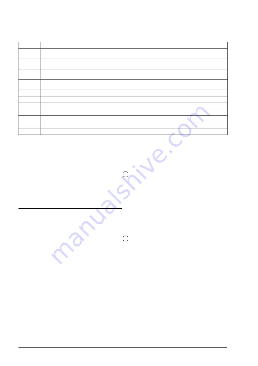
line. Table 3.3 lists the parameters determining the displayed value.
Table 3.3 - Setting the parameters displayed in the basic view
Parameter
Description
4.10
Number of the parameter from group 0 displayed in the
first line
of the
first screen
in the “basic view” when the
electric drive
does not operate
(STOP)
4.11
Number of the parameter from group 0 displayed in the
second line
of the
first screen
in the “basic view” when the
electric drive
does not operate
(STOP)
4.12
Number of the parameter from group 0 displayed in the
first line
of the
first screen
in the “basic view” when the
electric drive
works
(START)
4.13
Number of the parameter from group 0 displayed in the
second line
of the
first screen
in the “basic view” when the
electric drive
works
(START)
4.14
Number of the parameter from group 0 displayed in the
third line
of the
first screen
in the "Basic view".
4.15
Number of the parameter from group 0 displayed in the
first line
of the
second screen
in the "Basic view".
4.16
Number of the parameter from group 0 displayed in the
second
line of
the second screen
in the "Basic view".
4.17
Number of the parameter from group 0 displayed in the
third line
of the
second screen
in the "Basic view".
4.18
Number of the parameter from group 0 displayed in the
first line
of the
third screen
in the "Basic view".
4.19
Number of the parameter from group 0 displayed in the
second line
of the
third screen
in the "Basic view".
4.20
Number of the parameter from group 0 displayed in the
third line
of the
third screen
in the "Basic view".
3.5. Copying of parameters settings between drives
The control panel allows you to store 3 sets (SET 1, SET 2, SET 3) of all parameters of the converter for later
upload to the same or another converter of the same type.
Copying parameters from the converter to the control panel:
•
press and hold the „F” function key for 5 seconds -
4
on fig. 3.1,
•
select „
Copying parameters
” and confirm with the Enter key
„ ”
,
•
select „
Read from inverter
” and confirm with the Enter key
„ ”
,
•
choose one of the 3 sets of SET 1, SET 2, SET 3 to which the parameters will be saved
and confirm with the Enter key
„ ”
.
The copying process takes approximately 5 minutes.
Copying parameters from the control panel to the converter:
Attention:
1.
The inverter must be stopped (STOP) when uploading the parameter settings.
2.
Before starting the upload, make sure that the START command is not given from the terminal strip or through
one of the communication protocols.
In order to save the set of parameters to the converter, do the following:
•
press and hold the „F” function key for 5 seconds -
4
on fig. 3.1,
•
select „
Copying parameters
” and confirm with the Enter key
„ ”
,
•
select „
Save to inverter
” and confirm with the Enter key
„ ”
,
•
select one of the 3 sets of SET 1, SET 2, SET 3 from which, the previously saved parameters, will be
downloaded and confirm with the Enter key
„ ”
.
The copying process takes approximately 2 minutes.
3.6. Full pointers
Setting a parameter which is a pointer from outside the available range (e.g. setting par. 2.2 as “256 BL1”) is
allowed when function of full pointers is turned on (par.4.6 = 001 YES).
3.7. Restore factory settings
Factory settings can be restored only on the second PD access level 2. For this purpose, in the
"
4.2 Level/CODE
" parameter, enter the code corresponding to the second PD level 2 (default is 1). Then in par.
"
4.4 Fact.set.
" select one of the predefined factory sets (see section 7 “Sets of factory parameters”).
The drive usually comes with factory set no.1.
Note:
After loading any set of factory settings, the converter is automatically restarted, during which communication with
the keyboard is lost, and the following message appears on the display "
Communication failure. Please wait...
".
24
MFC710 User Manual - TWERD Power Electronics


