background image


SAFETY AND PREVENTION 


26/87 

   561405 - IS19/07 - EN 


3.5.2 

Lifting 


3.5.2.1 

Residue risks 

The lifting operations always involve a residual risk especially due to impacts, running over and/or crushing. These operations 
require a considerable degree of attention by the workers.  The machine weight is given in the technical data in § 2.1. 


Do not stand underneath the suspended load. 


No person should be near the machine during lifting. 

 
3.5.2.2 

Additional warnings 


Lift the machine only if clean. 


Lift the machine only if disconnected from any device/accessory (mortar conveying pipes, pneumatic pipes, 

wired-remote control, etc.), with engine off and battery cut-off switch disconnected. 


Use  suitable  lifting  means  with  capacities  compatible  with  the  machine  weight.  Observe  the  accident-

prevention regulations in the country of use. 


Only entrust qualified and authorised personnel with lifting operations. 


Only use the lifting points indicated by the related safety signals. 

 
3.5.2.3 

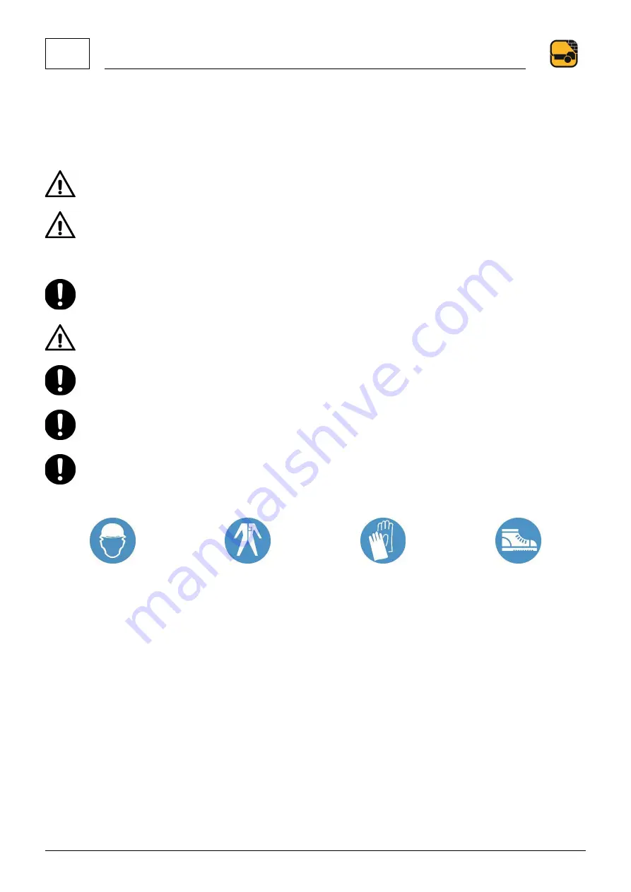
P.P.E. to be used 


Summary of Contents for TB30

Page 1: ...Serial number Year USE AND MAINTENANCE MANUAL TB30 IS19 07 561405 EN ORIGINAL ...

Page 2: ......

Page 3: ...19 3 SAFETY AND PREVENTION 20 3 1 DEFINITIONS 20 3 2 IMPORTANCE OF THE MANUAL 20 3 3 RECIPIENTS OF USE 21 3 4 MAIN WARNINGS 23 3 5 SPECIAL WARNINGS FOR THE WORK PHASES 24 3 6 SAFETY DEVICES 38 3 7 SIGNS ON THE MACHINE 40 4 TRANSPORT AND INSTALLATION 44 4 1 TRANSPORT AS ROAD TRAILER 44 4 2 LIFTING 48 4 3 INSTALLATION 49 5 USE AND OPERATION 54 5 1 ELECTRIC CONTROL BOARD 54 5 2 INSTRUMENTS ON THE MAC...

Page 4: ...6 MAINTENANCE 66 6 1 ROUTINE MAINTENANCE 66 6 2 PREPARING THE MACHINE FOR LONG PERIODS OF INACTIVITY 82 6 3 EXTRAORDINARY MAINTENANCE 83 7 DEMOLITION 84 8 TROUBLESHOOTING 86 ...

Page 5: ......

Page 6: ...liable and long lasting Even if you have used this type of machine before it is extremely important to be informed on the operation and features by the TURBOSOL PRODUZIONE S R L authorised technicians or by your Dealer once delivered By following these guidelines you will know how to get the best performances from this machine For any information please contact the TURBOSOL PRODUZIONE S R L Assist...

Page 7: ...of the machine F D S R 1 1 2 Machine plate The machine plate is affixed on the rear of the left side It bears the following information 1 CE Marking 7 Installed power 2 Manufacturer s company name and address 8 Power voltage 3 Type 9 Frequency 4 Serial no 10 Maximum pumping pressure 5 Year of manufacture 11 Maximum hydraulic system pressure 6 Weight 3 4 5 6 7 8 9 10 11 2 1 ...

Page 8: ...ation plate If the machine has been approved as road trailer the identification data is shown in plate 1 positioned inside the bonnet above the radiator It bears the following data 1 CE Approval no 4 Technically permissible maximum mass on the coupling point 2 Service identification no 5 Technically permissible maximum mass on the axis 3 Technically permissible maximum full load mass 6 Machine mod...

Page 9: ...ont beam is present in the versions fitted with road approved tow and repeated on the drawbar FIG 1 6 1 2 DOCUMENTATION ACCOMPANYING THE MACHINE The machine is delivered with the following documentation Use and Maintenance Manual EC Declaration of Conformity S P C Warranty certificate Engine Use and Maintenance Manual Trailer booklet System diagrams ...

Page 10: ...1 GENERAL INFORMATION 10 87 561405 IS19 07 EN 1 3 EC DECLARATION OF CONFORMITY FACSIMILE ...

Page 11: ... the declared faults be caused by the actions of the Purchaser its employees or third parties when the defect depends on bad use incorrect installation improper use or use that is not compliant with the instructions in the use and maintenance manuals received with the machine The warranty becomes void if the injection systems are damaged by unsuitable or polluted fuel in the event of faulty electr...

Page 12: ...description In this case if there are no interpretative doubts it is omitted in the text preceding the reference to the figure Where reference is made to the figure of another part of the Manual the reference is complete for example Fig 2 1 4 indicates part 4 of figure 1 of chapter 2 The tables are sequentially numbered by chapter The indication is placed under the table e g Tab 4 9 indicates tabl...

Page 13: ...GENERAL INFORMATION 1 561405 IS19 07 EN 13 87 ...

Page 14: ...ge battery charge hyd block bar 200 210 Pressure relief valve calibration Agitator water pump hopper discharge bar 185 190 Pressure reducer valve calibration S valve exchange battery charge hyd block bar 40 Maximum pump displacement regulator pressure bar 30 35 Pre charge pressure battery charge bar 140 MACHINE PERFORMANCE Maximum pumping pressure bar 80 Maximum flow rate m3 h 30 Maximum number of...

Page 15: ...l issued by the Italian Ministry of Transport 2 Respect the speed limits admitted in the country of use 3 The data refer to standard tyres SERVICE CONDITIONS Work environment Construction site outdoor Supporting ground conditions Horizontal Load bearing capacity of the supporting ground kN m2 3001 Gradient allowed during operation Longitudinal Degrees 5 Transversal Degrees 5 Room temperature Opera...

Page 16: ...er to cool and lubricate the pistons during their run is found between the concrete cylinders and the hydraulic cylinders Fresh concrete is poured inside the hopper the internal grid preventing oversized aggregate from entering is fitted with a vibrator to facilitate unload The concrete is firstly sucked inside the cylinders and then pumped towards the piping The alternating of sucking pumping is ...

Page 17: ...id 11 Vibrator device 3 Frame 12 Outriggers 4 Bodywork 13 Trailer drawbar 5 Discharge manifold 14 Parking brake as road trailer 6 Lifting ringbolt 15 Wheel 7 Engine cooling air socket 16 Parking wedges 8 Hopper agitator reducer 17 Lights bar as road trailer 9 Electric control board 18 Plate housing as road trailer ...

Page 18: ...egrated in the machine see attached manual 8 No 2 S valve drive hydraulic actuators 3 Discharge silencer 9 Lower hopper 4 Hydraulic valve unit 10 Hydraulic activation shutter for hopper discharge 5 No 2 hydraulic pumping actuators 11 Exchange S valve 6 Lubrication water tank 12 Product delivery manifold ...

Page 19: ...ct technical data 1 Concrete in general grout mixtures for micropiles 2 Grout spraying shotcrete for tunnels slopes embankments swimming pools channels consolidation and coverings All pumpable concrete can be strengthened with flexible or stiff fibres of adequate dimensions and features and sprayed with setting accelerator To avoid problems during pumping 1 the inert s maximum diameter must be bet...

Page 20: ...criteria required by the EU Directives and the relevant national regulations The Manual is an integral part of the machine and must be kept with care it must always be available at the workplace and accessible to anyone appointed to perform activities on the machine Replace the Manual if lost damaged or no longer legible The instructions in the Manual must be integrated with the laws on safety at ...

Page 21: ...ction refuelling etc and preliminary checks before starting the machine running the machine machine supervision during the work phases including cleaning cleaning the machine routine maintenance of the machine A second operator is required during the distribution and projection of the concrete whose tasks are distribution or projection of the concrete supervising the distribution or projection are...

Page 22: ...deteriorated structural parts within the dangerous processing area of the machine with fixed guards closed and locked and additional mobile guards closed or with mobile guards open and movement de energised and stopped in guaranteed safety or parts provided and indicated in the Manual The interventions can be for example a preparing the machine for commissioning or remove the blocks provided for t...

Page 23: ...xcept for that described in this Manual it is not permitted to use the machine beyond the provided limits Do not perform changes transformations or applications on the machine that might compromise its safety The machine must not be misused in particular it cannot be operated with different parameters to those specified and with materials sized or weighing more than the machine capacity The machin...

Page 24: ...de in the country of use Also secure the accessories provided with the machine pipes accessory box etc Avoid unexpected movements Use the drawbar to manually move the machine or hook the ball joint to an adequate device No one except the personnel appointed by the user should be within the action range of the moving machine during transportation The machine weight and the trailer limits of use are...

Page 25: ...hten the wheel fixing studs after a distance of at least 20 km and at most 100 km To reduce the formation of white rust on the galvanised parts of the trailer keep the machine in a ventilated place after winter trips clean the galvanised components with clear water e g steam jet All extraordinary maintenance repairs and installation of new parts must be performed by personnel authorised by the tra...

Page 26: ...be near the machine during lifting 3 5 2 2 Additional warnings Lift the machine only if clean Lift the machine only if disconnected from any device accessory mortar conveying pipes pneumatic pipes wired remote control etc with engine off and battery cut off switch disconnected Use suitable lifting means with capacities compatible with the machine weight Observe the accident prevention regulations ...

Page 27: ...ty before positioning the machine The work place must comply with the accident prevention regulations in the country of use Observe the safety distances from the boundaries of the worksite or from uneven ground Observe the safety distances from the live parts of power lines Position the machine on a levelled surface and consistent ground The machine cannot be used in environments where there are p...

Page 28: ...ve the failures It is forbidden to use the machine when it is not under the normal operational conditions provided Do not use the machine with the mobile and fixed protection guards open not properly secured or removed Only use the machine if the safety devices are in perfect working conditions Do not use the machine with the protection and or safety devices off and or not working DANGERS ARISING ...

Page 29: ...lace with new and original ones The control procedure is described in the maintenance chapter Check the rubber gasket is present fully fasten the lever and insert the safety pin when connecting the piping segments Fig 3 4 1 2 3 3 Do not disconnect the material conveying pipes from the machine if they are pressurised Always discharge the residue pressure and then disconnect them In the absence of p...

Page 30: ...M INADEQUATE LIGHTING The service conditions indicate the lighting required in the work environment Greater lighting in the work environment may be required during certain operations such as for example routine and extraordinary maintenance If the lighting of the work environment fails it is necessary to stop working and restore adequate lighting DANGERS ARISING FROM A REASONABLY FORESEEABLE MISUS...

Page 31: ...ENTION 3 561405 IS19 07 EN 31 87 Make sure that switching on the machine does not endanger anyone Stop the machine by pressing the emergency button only in emergencies or dangerous situations 3 5 4 3 P P E to be used ...

Page 32: ...tion of the respiratory tract Move the person concerned outdoors In case of ingestion take the person concerned to the hospital immediately Do not induce vomiting to avoid the risk of aspiration in the respiratory tract In case of contact with the skin take off the contaminated clothing Thoroughly wash the contaminated parts with soap and water In case of contact with eyes rinse immediately with p...

Page 33: ...qualified personnel and authorised by the engine Manufacturer Do not use petrol as fuel To avoid fires keep the engine clean and without dirt grease and waste Wear suitable accident prevention clothing when handling the engine fluids and spare parts anti freeze oil filters etc ELECTRICAL HAZARDS The electrical hazards arise from the electrical system maintenance operations and are electrocution ch...

Page 34: ...achine even if only one pipe is disconnected Disconnect the battery cut out switch before working on the plant Repairs and extraordinary maintenance must be performed by authorised maintenance technicians Pressurised fluid jets can penetrate the skin and cause damage Before disconnecting any pipe make sure there is no residual pressure inside the circuit pressure gauge must be at zero bar Wear ade...

Page 35: ...ed out it must be evident e g through warning signs that the machine is under maintenance and that it cannot be used normally Immediately replace the faulty components involved in the safety functions These components must be replaced by maintenance technicians authorised by the Manufacturer If it became necessary to neutralise the safety systems interlocked fixed guards safety switches etc restor...

Page 36: ...corrosive Do not inhale the gases Wear adequate accident prevention clothing when before handling the electrolyte DANGERS ARISING FROM THE DISASSEMBLY OF MECHANICAL PARTS IN GENERAL The risks associated with the disassembly of machine parts are cut entrapment falling impact and crushing dangers arising from handling lubricant fluids Handle the parts being disassembled with care and attention move ...

Page 37: ...lves Wear adequate accident prevention clothing gloves goggles 3 5 6 2 Additional warnings Cordon off the area where the disposal is carried out it must be evident e g through warning signs that the machine cannot be used normally If it is necessary to intervene under the machine make sure that it is fixed and secured 3 5 6 3 P P E to be used ...

Page 38: ...9 1 2008 Avoids exposure to moving parts The solenoid valve controlling the pumping is de energised when the grid is opened When the grid is opened the moving parts stop in a very short time less than 1 sec The pumping can only be started if the grid is closed and the controls enable button pressed 5 HOPPER BASE Fixed guard Shaped steel sheet panels fastened with screws to the machine structure fo...

Page 39: ... is only permitted to the maintenance technician In any event the operator must never attempt to open a fixed guard 4 it is not possible to reassemble a guard in the wrong position so as to leave dangerous openings in the fairing 5 if the guards are not secured in their seats with the special screws they cannot remain apparently closed and resting in that seat without the fixing elements 6 in case...

Page 40: ... The obligation sign has a blue background and white mark These labels are placed on the machine parts where there is a residual risk Information They inform the operator on specific functions These labels are positioned immediately near the element to which they refer The machine controls are described in 5 3 Keep the signs clean It is forbidden to remove the signs Replace worn and or illegible s...

Page 41: ... Safety footwear Protect the respiratory tracts mask Category II Eye protection Hearing protection Read the use and maintenance manual before working Maintenance performed only by qualified personnel Lifting points INFORMATION Chassis mass Water connection High pressure washer delivery Grease Lubricant oil Remote control connection ...

Page 42: ...3 SAFETY AND PREVENTION 42 87 561405 IS19 07 EN ...

Page 43: ...SAFETY AND PREVENTION 3 561405 IS19 07 EN 43 87 ...

Page 44: ...d maintenance manual of the road tow Turn off the engine remove the keys from the electrical panel deactivate the battery cut off switch and fasten the doors Remove all accessories connected to the machine pipes wired remote control etc Only machines fitted with frame in road towing version can travel on public roads Respect the highway code when towing the machine The machine cannot be used for t...

Page 45: ...nnected to the towing vehicle and is working the tyre pressure is correct the feet are fully raised Fig 4 5 4 1 2 Connect the trailer Adjust the drawbar height a Remove the safety split pins 1 Fig 4 6 b Loosen the locking handles 2 Fig 4 6 until rotation between the drawbar sections is possible c Adjust the angle of the sections only by acting on handle 4 Fig 4 6 so that the end is horizontally ho...

Page 46: ...ble Connect the lights power supply cable to the towing vehicle Introduce the pull cable in the appropriate cable guide eyelet FIG 4 8 Remove the wheels parking wedges and place them in their housing Release the parking brake 5 Fig 4 6 from the wheels 4 1 3 Release the trailer Disconnect the lights power supply cable from the towing vehicle lower the outrigger feet to the ground lift the ball join...

Page 47: ...tally activate the brake House the cable around the towing hook s stem if without appropriate drive eyelet and hook the snap hook on the cable itself FIG 4 8 The cable activates the parking brake emergency brake should the trailer accidentally detach from the drive The cable must be correctly introduced inside the cable guide ring to guarantee excellent emergency brake operation ...

Page 48: ...uctures always make sure that the handling area is not occupied by personnel or objects that may be cause of danger Do not move any structure in case of poor lighting and or visibility until a supervisor has ascertained the necessary freedom of movement within the work area do not assume that the work area is free but always visually ascertain it Electrically and mechanically block all moving part...

Page 49: ...lace barriers and warning signs around the work area of the machine near traffic routes or pedestrian passages so as to prevent any person or mean access to the area No one except the operator responsible for the machine and its functionality must remain near the work area of the machine Bring the machine to the work position and make sure the ground is firm and flat Make sure that there are no pe...

Page 50: ...cribed to pump material horizontally Vertical pumping The vertical piping section must be fixed and supported using the appropriate collars FIG 4 11 Downward pumping The downward piping section must be fixed and supported using the appropriate collars FIG 4 12 Arrangements must be made to stop the concrete fall in the downward section e g assemble a bend or S bend as in FIG 4 12 or make tilted sec...

Page 51: ...RANSPORT AND INSTALLATION 4 561405 IS19 07 EN 51 87 1 2 BOIACCA SPUGNE DI LAVAGGIO Connect the pipes ensuring the presence of gasket 1 fully tighten fittings 2 and secure them with split pins 3 Fig 4 14 ...

Page 52: ...4 TRANSPORT AND INSTALLATION 52 87 561405 IS19 07 EN 1 2 3 3 Connect the mortar conveyor piping 1 Fig 4 15 1 ...

Page 53: ...TRANSPORT AND INSTALLATION 4 561405 IS19 07 EN 53 87 ...

Page 54: ...e pumping is inhibited when the hopper grid is opened To restore the function close the grid and press the button The indicator light 10 lights up when the safety devices intervene the indicator light turns off after closing the grid and pressing the button 4 PUMPING Stable position The pumping is enabled in this position The pumping is started and stopped by means of the remote control via cable ...

Page 55: ...ic oil temperature the control system stops the engine after 5 seconds from switch on 13 GLOW PLUGS PRE HEAT INDICATOR YELLOW When lit the glow plugs pre heat is on the engine can be started when the indicator turns off 14 ENGINE COOLING LIQUID TEMPERATURE INDICATOR RED When lit during the engine operation it indicates high cooling liquid temperature the control system stops the engine after 5 sec...

Page 56: ...5 USE AND OPERATION 56 87 561405 IS19 07 EN 5 2 INSTRUMENTS ON THE MACHINE ...

Page 57: ... the material in the hopper is activated Stable position Reversal In this position the agitation reversal of the material in the hopper is activated 8 HIGH PRESSURE WASHER LEVER Stable position Activating the lever activates the high pressure washer 9 HOPPER DISCHARGE LEVER Unstable position Activating and holding the lever opens closes the hopper discharge shutter 10 BATTERY CUT OFF SWITCH It is ...

Page 58: ...ector 7 FIG 5 1 Press START button 3 FIG 4 16 to enable the functions of the remote control via cable Place the selector at 4 FIG 4 16 to enable pumping stable command Place the selector at 5 FIG 4 16 to reverse pumping stable command The selector s neutral position blocks pumping Place selector 6 FIG 4 16 at 1 to enable the vibrator at 0 to disable it stable command Press button 7 FIG 4 16 to mak...

Page 59: ...TION OF GROUT PIPES Package an adequate amount of grout water and cement pumping up to 20 m 40 50 litres pumping beyond 20 m 50 80 litres Pour the grout in the hopper Activate the agitator by placing lever 7 FIG 5 2 hopper side in stable position Anti clockwise rotation During the heating phase do not use the machine at maximum load Heat the oil by running the machine for about 10 minutes depends ...

Page 60: ...cuit oil varies based on used mix and layout of the piping line During the S valve exchange phase pressure gauge 2 FIG 5 2 indicates the operating pressure of the hydraulic jacks controlling the S valve The auxiliary circuit pressure gauge 3 FIG 5 2 indicates the services work pressure agitator material discharge shutter high pressure washer that must be below 180 bar Should only the agitator be o...

Page 61: ...ty for at least 5 minutes this decreases the operating temperature Always perform this operation unless a dangerous situation occurs requiring an emergency stop 5 7 REFUELLING Use approved containers Do not use buckets bottles jars etc Do not smoke or generate open flames or sparks in the work area Do not mix petrol or alcohol with diesel fuel The mixture can cause fires and serious damage to the ...

Page 62: ...y in correspondence of the fittings Steel pipes clogging The obstruction is located by the noise emitted upon impact of the iron hammer against the pipe a metallic sound is heard if the pipe is not clogged whereas a plonking sound is heard if the pipe is clogged Disconnect the clogged pipe from the piping line once this has been pre emptively depressurised Place the pipe vertically to evacuate its...

Page 63: ...enance technician Ensure there is no ice inside the pump if using at extremely low temperatures The inner diameter of the suction pipes must not be smaller than the suction fitting Fig 5 4 and must have a rated pressure of less than 10 bar Firmly grasp the water gun and pay attention to the reaction force of the water jet Do not direct the jet towards materials containing health damaging substance...

Page 64: ...5 USE AND OPERATION 64 87 561405 IS19 07 EN Connect the water intake pipe to the supply fitting 1 FIG 5 4 Connect the high pressure delivery pipe to the fitting 2 FIG 5 4 ...

Page 65: ...manifold Activate reverse pumping Stop the engine Open the bottom flap and discharge the hopper Continue for some cycles until only clear water comes out from the hopper Cover the hopper and S valve walls with oil or other lubricant in this way the mix inside the hopper has less possibilities of forming deposits upon subsequent work session We recomend covering the hopper with a tarpaulin to avoid...

Page 66: ... 6 1 2 X Engine oil level check 6 1 3 Man Engine X Fittings and mortar conveying pipe check 6 1 4 X Conveying pipe anchor check 6 1 5 X Machine and accessories cleanliness 5 10 X Greasing 6 1 6 X Wheel studs tightness check Man Tow X1 Visual inspection of road trailer for visible damages Man Tow X Ball joint lubrication and greasing 6 1 7 Man Tow X Trailer drawbar cogwheels joints cleanliness 6 1 ...

Page 67: ...TION Check the sealing surfaces of the cartridge for damage Hold the cartridge against the light or pass a bulb inside it to see if t he paper is slit or damaged Replace the cartridges observing the frequencies indicated in Tab 6 1 6 1 2 Hydraulic oil level check When When beginning work Machine state With machine off and cold Tools Visual inspection None Top up No 10 wrench and funnel The oil lev...

Page 68: ...uced it is possible that the engine is not working properly Contact the Dealer the TURBOSOL PRODUZIONE S R L technical assistance or an authorised workshop directly 6 1 4 Fittings and material conveying pipe check When When beginning work Pipe state Clean disconnected from the machine Tools Visual inspection None The conveying pipe could be composed of a iron hose or rubber hose to the ends of whi...

Page 69: ...ing work Anchor state Clean not released from the conveying pipes Tools Visual inspection None Check the good condition of the anchors the metal parts must not be damaged or rusty If the anchors are damaged or you are not sure of their good condition replace them with new and original ones ...

Page 70: ...ort 3 Blind side agitator support 4 Exchange jacks lever and S valve support 5 Exchange jacks tilting support 6 Exchange jacks joints 7 Pumping barrels 8 Delivery flange opening joint if present For the lubrication of the pumping barrels it is necessary to bring the rubber piston to start and then step 7 Repeat the operation with the second rubber piston If the agitator supports and the S valve ar...

Page 71: ...off and cold Tools Grease and lubricant indicated in 2 1 Grease the ball seat and lubricate the joints Fig 6 6 ALWAYS REFER TO THE USE AND MAINTENANCE MANUAL OF THE ROAD TOW 6 1 8 Cleaning of the cogwheels joints of the trailer drawbar When Before manual towing Machine state With machine off and cold Tools Brush or cloth Clean the cogwheels at the ends of the drawbar sections Fig 6 7 ...

Page 72: ... to fix the battery No 10 wrench for the battery poles Check that the battery cut off switch is disconnected Disconnect the negative pole 1 the positive pole 2 and disassemble the battery stop 3 Fig 6 8 Replace the battery with a new and original one or with one having features not inferior to those indicated in the technical data Reassemble the stop reconnect the positive pole and the negative po...

Page 73: ...d with cold weather Respect the safety sheets of the chosen anti freeze during use and the laws in force with regard to the disposal of such substances We recommend emptying the bowl each working day Water in the bowl must be changed when showing fine sediments ...

Page 74: ...ical block fixing screw Turn on the machine place the flow rate regulator at minimum Activate the pumping system until one of the two pistons reaches stroke end so as to clearly see the spacer fitting in the centre of the bowl Fig 6 10 Turn off the machine from the main board and put the key in your pocket operation to be performed whenever you are about to manually work on the pumping unit or on ...

Page 75: ...ibute grease to lubricate the pistons it is good practice to put more grease the excess will disappear during installation Place the piston in front of the pumping barrel and insert it slowly if necessary use a small hammer With the piston inserted insert the spacer fittings and tighten the screws and bolts Always connect the spacer fitting to the piston and only then to the hydraulic piston stem ...

Page 76: ...cumulator discharge valve to remove pressure from the circuit as indicated in paragraph 6 1 12 FIG 6 11 WEAR DISC REPLACEMENT Disassemble the side carter 1 FIG 6 13 by loosening the bolts with a 10 mm key Disassemble the upper hopper 2 FIG 6 13 by loosening the six bolts with a 19 mm key Remove the anti rotation lock bracket 2 FIG 6 14 by loosening bolt 1 FIG 6 14 with 17 mm key ...

Page 77: ...MAINTENANCE 6 561405 IS19 07 EN 77 87 Loosen bolt 1 FIG 6 15 by extracting it by about 15 20 mm with 65 mm or adjustable key Remove the rigid greasing duct from fitting 1 FIG 6 16 with 12 mm key ...

Page 78: ...osen the delivery flange by about 15 20 mm by loosening the six bolts with 30 mm key and making leverage on the S valve using a piece of wood FIG 6 17 Attention Do not remove the flange completely Extract the wear disc to be replaced FIG 6 18 ...

Page 79: ...Insert the new wear disc with the new compensation gasket FIG 6 19 WEAR PLATE REPLACEMENT Disassemble the wear plate by loosening the three bolts using 24 mm key FIG 6 20 Replace the wear plate with a new one and fix it with the three bolts ...

Page 80: ...g washing and material outflowing between the same components and during pumping show the non perfect seal S valve adjustment is indicatively carried out where distance between wear plate and disc exceeds 0 25 mm or if the S valve is repeatedly clogged Tighten the S valve adjustment bolt 1 FIG 6 21 with 65 mm or adjustable key When the bolt starts to resist further tighten by 60 120 reassemble and...

Page 81: ...e delivery flange 1 FIG 6 23 by tightening the six bolts with 30 mm key Reconnect the rigid duct for greasing 2 FIG 6 23 to the fitting on the delivery flange Start the machine and check the S valve regularly exchanges with the engine at minimum ...

Page 82: ... empty the fuel tank disconnect the battery grease the machine through the lubricators and or centralised greasing system and separately grease the S valve wear disc plate RESTART AFTER LONG PERIODS OF INACTIVITY The following precautions must be taken when the machine is put back into operation after a long period of inactivity drain the condensate from the hydraulic tank check the hydraulic oil ...

Page 83: ...ngine oil Engine oil filter cartridge Fuel filter cartridge Hydraulic oil Hydraulic oil filter Filler cap and oil tank vent Engine Engine supports Hydraulic system Safety system elements Trailer 1 2 Engine air intake pipe Fuel pipes and tightening clamps Oil tank breather cap Electrical system Battery electrolyte Battery terminals Battery charge status Material conveyor fittings and pipes Machine ...

Page 84: ... 3 The operations to be performed are those for the scrapping of steel copper aluminium parts metal alloys in general rubber and plastic compounds insulating materials lubricating materials batteries and their fluids etc The machine demolition and disposal must be carried out according to law ...

Page 85: ...DEMOLITION 7 561405 IS19 07 EN 85 87 ...

Page 86: ... the diesel oil filters Diesel oil tank in reserve Add diesel oil Clogged air filter Clean or replace the air filter The pumping does not work Open hopper grid Close the grid Emergency button pressed in this case the engine turns off Release the emergency button after ascertaining that the machine can safely resume work Clogging along the concrete pipe the hydraulic oil pressure is constantly at m...

Page 87: ...TROUBLESHOOTING 8 561405 IS19 07 EN 87 87 ...

Reviews: