Tubeline TL60ECV Operator'S Manual Download Page 50

TL60ECV

 - 

Section 16: Option - Dispatch Arm 16-1

Section 16: Option - Dispatch Arm

Dispatch Arm Installation

Refer to 

Parts Manual

 to ensure all parts have been received.

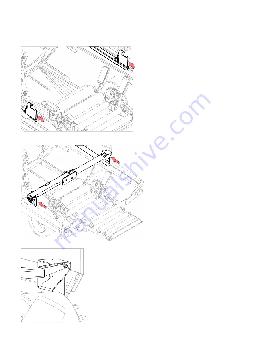
1.  Remove standard last bale pushoff hooks 

from ram tubes. Keep unfastened hardware. 

See 

Fig.1

.

2.  Insert right dispatch arm pocket into right ram 

tube. Lock with existing bolt and nut. See 

Fig.2

.

3.  Use a lifting device to raise dispatch arm 

assembly.

4.  Slide dispatch arm into left ram tube. Bolt 

with existing bolt and nut.

5. 

Lower dispatch arm to ensure it fits into right 

side pocket. See 

Fig.3

.

Fig .2

Fig .3

Fig .1

Summary of Contents for TL60ECV

Page 1: ...ine Manufacturing Limited 6455 Reid Woods Drive RR 4 Elmira Ontario Canada N3B 2Z3 Email sales tubeline ca Fax 519 669 5808 Tel 519 669 9488 Toll free North America 1 888 856 6613 www tubeline ca Do n...

Page 2: ...als are printed and shipped with machines as they leave the manufacturer Your machine may include parts or features not yet included in the initally shipped manual The latest manual version can be fou...

Page 3: ...res batteries electrical components hydraulics and engines The buyer by the acceptance of the equipment will assume all liability for any damages which may result from accident abuse or misuse by his...

Page 4: ...nes 2 1 Personal Protective Equipment 2 2 Lighting 2 2 Safety Decal Locations 2 4 Safety Decal Illustrations 2 5 Section 3 Setup 3 1 Dealer Installation 3 1 Battery Hookup 3 2 Pre Operating Inspection...

Page 5: ...1 Plastic Film Disposal 9 1 Section 10 Maintenance 10 1 Grease Points 10 1 Grease Timeline 10 2 Hydraulic Oil 10 2 Hydraulic Oil Filter 10 2 Section 11 Diagnostics 11 1 Manifold Solenoid Functions 11...

Page 6: ...e Roller Kit 17 1 Guide Roller Kit Installation 17 1 Section 18 Option Night Light Kit 18 1 Night Light Kit Installation 18 1 Night Light Kit Operation 18 1 Section 19 Option Twin Wrap Kit 19 1 Twin W...

Page 7: ...Intentionally Left Blank...

Page 8: ...thin four hours In an emergency the bales can be left 12 to 16 hours The Tubeline wrapper makes timely harvest possible by reducing the dependence on the weather It is much easier to get to wilt silag...

Page 9: ...from a forward pointed position while towing this machine Front Rear Left Right Terminology Common terms used in this manual Bale Ram Bale Deck Bale Trigger Hoop Plastic Film Wrap Chamber Left Safety...

Page 10: ...hat needs to be avoided Operator needs to be aware of these dangers High probability of serious injury or death NOTE Indicates an informative non safety related message Safety Guidelines Take the nece...

Page 11: ...ng when operating of maintaining the TL50SLV Lighting This machine is equipped with lights and reflectors as required by the most stringent government and ASAE specifications They connect to power uni...

Page 12: ...TL60ECV Section 2 Safety 2 3 Clearance Markers Part No DEAMBER Part No DERED...

Page 13: ...2 4 Section 2 Safety TL60ECV Safety Decal Locations NOTE Decals shown are not to scale...

Page 14: ...l 5 1 DE30871 Oil Fill Cap Decal 6 1 DE30879 Remote Control Decal 7 1 DE30880 Battery Boost Decal 8 2 DE30881 Tape Holder Decal 9 1 DE41713H ISO Decal High Pressure Fluid Horizontal 10 1 DE41714S ISO...

Page 15: ...e Control Enclosed decal Part No DE30880 Item 7 Positive charging terminal for use a battery boost Part No DE30881 Item 8 Wrap tape can be stored on this holder Part No DE41713H Item 9 Do not use hand...

Page 16: ...9 Item 19 Keep clear of wheels when machine in operation and transportation Part No DE43873S Item 20 Turn control panel to manual wrap mode MAN before starting engine Part No DE41924 Item 13 Remove pi...

Page 17: ...off engine power and control panel before boosting battery Part No DECANADA Item 23 See pg I Manufacturer of origin decal Part No DE43875H Item 22 Use handle when lowering pivoting safety guard to av...

Page 18: ...r roller bed 3 Install bottom safety guard mounts using bolts washers and nuts Left side shown in Fig 1 right side is the same 4 Install left safety guard by bolting at pivot point Do not over tighten...

Page 19: ...ching battery terminal A 3 Confirm TL60ECV s functions are working properly Refer to Control Screen Operations pg 6 1 Battery Hookup A 9 Install right maintenance safety guard by bolting at pivot poin...

Page 20: ...am to front of bale wrapper Home position by turning FWD REV bale ram switch to FWD forward Auto Mode Test Run Test machine in Auto mode without bales and without plastic film rolls installed 1 Switch...

Page 21: ...ooperator may set a new bale on the table or engage wrap cycle with remote Plastic has a natural tack In the event of the plastic being stored for an extended period of time the tack may migrate to th...

Page 22: ...r of plastic wrap carrier See Fig 4 6 Remove empty plastic wrap cartridge from plastic wrap carrier by compressing sliding spring spool 7 Press one end of new plastic wrap roll into sliding spring spo...

Page 23: ...to resume wrap operation See Fig 1 12 Route loose end of plastic wrap roll through 3 bottom rollers as shown in Fig 6 and decal located on rear side of plastic wrap carrier See Fig 5 13 Tie loose end...

Page 24: ...er settings firmness weight etc 2 Pull pin out and rotate clockwise to lock in open position See Fig 1 3 Use handle to move bale saddle to desired position aligning outside edge of bale saddle front p...

Page 25: ...4 Engine Remote Start Rocker Switch Default set to Key Switch Toggle switch to Remote if bale wrapper is equipped with an optional remote control when desired Refer to Section 13 for further details 5...

Page 26: ...arameters screen 4 Selector Knob Turn to move to different selection press to select a box for edit Rotate knob to modify value of selected box Press again to set value and deselect box 1 Wrap Mode Fu...

Page 27: ...chamber 4 Roller Bed Up Press and hold to raise rear roller bed to full height 5 Roller Bed Down Button Press and hold to lower rear roller bed to ground 6 Ram Forward Button Press and hold to retrac...

Page 28: ...ount from 2 20 layers per bale 3 Enable Disable the film sensor option as needed see pg 14 1 4 Adjust time before power drive option auto disengages Default is 10 seconds 5 Turn off or change facing d...

Page 29: ...eters Screen From activated Wrap Mode screen press Next button three times to reach the Parameters screen This screen is used to enable disable installed options Non labelled boxes are informative onl...

Page 30: ...trol screen Refer to pg 6 1 3 Fold tongue and pin to steering slider tube See Fig 1 4 Confirm balewrapper is steering straight 5 Place several unwrapped bales at end of row to act as stop thus creatin...

Page 31: ...r from drifting out of line NOTE Prevent air pockets in bale row by avoiding sharp turns Steering can be done remotely with optional remote control Refer to pg 13 1 Manual steering is not required wit...

Page 32: ...bale spoil 4 Place last bale on bale deck and manually push and wrap bale See Fig 1 5 Stop the ram and wrap several more layers on the end of the bale 6 Cut plastic film by pressing and holding the f...

Page 33: ...be from its mounts on right side of the wrapper and lay it across the top of the pushoff hooks See Fig 6 NOTE Replace the pin in holder to avoid losing it Fig 6 16 Run the bale ram once more to comple...

Page 34: ...Shutoff 13hp Engine Only Undo steering unfold tongue and insert lock pin Hitch tongue A to power unit drawbar with pin Fasten safety chain B securely to power unit Insert balewrapper s 7 pin connecto...

Page 35: ...Reduce speed when towing under adverse surface conditions when turning and when on inclines Do not attempt transport if the fully loaded implement weighs more than 1 5 times the weight of the tractor...

Page 36: ...neral exposed end bale will not spoil for 1 2 days in warmer weather and at least a week in colder weather Remainder of wrapped bale row should not spoil with an exposed end Plastic Film Disposal Foll...

Page 37: ...10 1 Section 10 Maintenance TL60ECV Section 10 Maintenance Grease Points Grease decals on machine signify an area to occasionally grease Use a high quality EP grease...

Page 38: ...apper under the bale deck Check oil level gauge from right side of machine see Fig 1 Fill through cap mounted on rear of right fender see Fig 2 Leave about 1 4 from top of sight guage to avoid overflo...

Page 39: ...11 1 Section 11 Diagnostics TL60ECV Section 11 Diagnostics Manifold Solenoid Functions...

Page 40: ...the plastic is properly routed through the carrier rollers Install the plastic film rolls according to the Plastic Installation diagram refer to pg 4 1 3 Plastic film carrier rollers not turning freel...

Page 41: ...the hose currently in the P port located on the rear of the manifold valve 2 Loosen and remove the 3 bolts from the same side as Step 1 fig 1 on next page 3 Bolt the new Power Drive Manifold PDM to re...

Page 42: ...rim gear by engaging disengaging parking brake handle 4 Route two supplied hoses from main manifold valve ports DR and DF along front of oil tank then through hoop wheel mount and side frame tube to m...

Page 43: ...nuts See Parts Manual for full assembly breakdown NOTE Right rear tire may need to removed 4 Ensure power drive gear sprockets mesh with rim gears by engaging disengaging handles 5 Route hoses from m...

Page 44: ...ation Enable powerdrive on control screen Parameters page as seen on pg 6 4 Powerdrive is only available when machine is in Auto Wrap Mode Press button on control screen to enable the Power Drive opti...

Page 45: ...h to Remote Engine Start ON OFF Turns handheld unit on off detent has no function START Starts the wrap cycle unplug the table switch if you prefer to start each cycle with this button this will not r...

Page 46: ...djustment can be made on the bracket and on the sensor wire The end of the sensor wire behind the switch can be bent to allow the wire in front of the switch to drop down far enough to trip the switch...

Page 47: ...eration Change Film Sensor field to Enabled on control panel screen See pg 6 3 Make sure plastic film sensor wire is on top of plastic film after installing new plastic rolls Plastic film sensor wire...

Page 48: ...pplied harness into bottom of reciever board casing 3 Follow the diagram in Fig 2 to wire the loose wire harness ends into bale wrapper s main wiring harness The cable wires marked ECU must be inserte...

Page 49: ...rrier frame so that when transmitter is mounted it is 1 16 from tip of rare earth magnet See Fig 2 4 Install transmitters on each plastic wrap carrier frame with provided machine screws and lock nuts...

Page 50: ...t bale pushoff hooks from ram tubes Keep unfastened hardware See Fig 1 2 Insert right dispatch arm pocket into right ram tube Lock with existing bolt and nut See Fig 2 3 Use a lifting device to raise...

Page 51: ...handle to unfold and lower the dispatch arm across the roller bed and into right side pocket 3 Finish bale row as instructed in Ending Bale Row pg 7 3 4 Raise dispatch arm to folded position with han...

Page 52: ...option allows for better bale row alignment and may be necessary in uneven wrapping situations Guide Roller Kit Installation Refer to Parts Manual to ensure all parts are included 1 Slide left and ri...

Page 53: ...ety guard mount with provided hardware See Fig 1 2 Install right on top of right safety guard mount with provided hardware 3 Route night light kit wiring harness through large hole in top of safety gu...

Page 54: ...f standard plastic film carrier 4 Bolt in place with provided hardware Handles must be placed through top side and fully tightened 5 The 3 socket head bolts must be placed through bottom side Do not f...

Page 55: ...4 Insert new plastic film roll into front spool holder 5 Align other end of plastic film roll with spring spool holder 6 Push spring spool holder into plastic film roll ensure latch snaps into locked...

Page 56: ...nt steering cylinder rod end in place will need to be removed to allow the laser sensor mount bracket to slide between the cylinder rod end and the sliding tube lug 2 Reinstall cylinder pin 3 The comm...

Page 57: ...he sensor to its mounting plate should fit neatly into the pivot plate to lock the necessary position in place 3 After setting the laser eye to the desired direction go to the control panel screen Set...

Page 58: ...deck while placing bales Suspension Axle Installation WARNING Do not attempt this installation without properly bracing the machine and blocking wheels to prevent rolling Install while machine on fla...

Page 59: ...VII Imperial Torque Value Chart TL60ECV Imperial Torque Value Chart...

Page 60: ...TL60ECV Metric Torque Value Chart VIII Metric Torque Value Chart...

Page 61: ...Installation 14 1 Fuel Shutoff 13hp Engine Only 8 1 General Button Functions 6 1 Grease Points 10 1 Grease Timeline 10 2 Guide Roller Kit Installation 17 1 Hydraulic Oil 10 2 Hydraulic Oil Filter 10...

Page 62: ...1 1 Section 2 Safety 2 1 Section 3 Setup 3 1 Section 4 Adjustments 4 1 Section 5 Control Panel Operation 5 1 Section 6 Control Screen Operation 6 1 Section 7 Operation 7 1 Section 8 Transporting Bale...

Page 63: ...ransport Lock 8 1 Troubleshoot Plastic Film and Carriers 11 2 Twin Wrap Kit Adjustments 19 1 Twin Wrap Kit Installation 19 1 Twin Wrap Plastic Film 19 2 Usage 1 1 Wireless Film Sensor Operation 15 2 W...

Page 64: ...WARNING The engine exhaust from this product contains chemi cals known in the state of California to cause cancer birth defects or other reproductive harm...

Reviews: