


44
D01-051en202111 Manual TriBox3
Use
Malfunction &
Maintenance
Commis-
sioning
Introduction
General
Information
FA
Q
Technical Data
W
arranty
Customer
Service
Contact
Keyword
Index
Accessories
Advanced
Use
Advanced Use
//
TriBox3
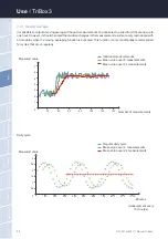
In the lower area, you can have a fixed value held for the respective interface for test purposes.
The TriBox3 has six analog outputs which provide 4...20 mA to the work area. The measured values can be
transmitted in freely selectable scaling via the analogue interface to other systems, for example process control
systems.
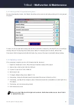
1.
Carefully remove the aluminium panels on both sides of the device.
2.
Remove the four screws on the edge of the TriBox3 with a Phillips screwdriver.
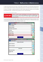
Please note that only passive components are connected to the analog outputs so
that no external voltage can enter. This could damage the TriBox3.
Danger to life due to electric shock! Due to the free mains voltage in the unit,
installation work may only be carried out by qualified personnel who are au
-
thorised to do so on the basis of their training. The relevant safety and VDE
regulations must be observed. Before opening the unit, disconnect it from
the power supply and secure it against being switched on again.
DANGER
NOTICE
3.
After removing the four screws, carefully open the cover of the housing upwards. The housing cover
must be able to be opened without resistance and without the use of force, otherwise there is a risk of
damaging the wires in the device.
Summary of Contents for TriBox3
Page 1: ...TriBox3 OPERATING INSTRUCTIONS...
Page 2: ......


