52
Low Ambient Damper Adjustment
(Factory or Field Installed)
When a unit is ordered with the low ambient option (i.e.,
Digit 11 is a “1” in the model number), a damper is factory
installed over the lead condenser fan for each refrigeration
circuit. Refer to the appropriate unit illustrated in Figure 5-3
for the damper locations.
For field installation, mount the dampers over the con-
denser fans at the locations shown in Figure 5-3 and con-
nect the actuator, controller, and sensor for each circuit.
(Refer to the Installation Instructions provided with each low
ambient damper kit.)
The controller has a factory default setpoint of 105
o
F. This
setpoint can be adjusted by installing a field supplied resis-
tor on 2TB34 in the low ambient control panel located in the
back of the main control panel. (See the low ambient wiring
diagram, that shipped with the unit or with the field kit, for
resistance values and installation location.)
Inspect the damper blades for proper alignment and opera-
tion. Dampers should be in the closed position during the
“Off” cycle. If adjustment is required;
1. Remove the sensor leads from the input terminals 6
and 7 for circuit #1 and/or 11 and 12 for circuit #2.
(Controller output signal will go to 0.0 VDC and the
damper will drive to the closed position.)
2. Loosen the damper shaft “Locking” set screws on
the actuator
3. Firmly hold the damper blades in the closed position
4. Retighten the “Locking” set screws.
To check damper operation, jumper between the sensor in-
put terminals 6 and 7 and/or 11 and 12 (if applicable). Con-
troller output signal will go to 10 VDC and the damper will
drive to the full open position.
EVP Chiller Applications
Start the chilled water circulating pump by closing the field
provided pump disconnect switch and turn the pump control
circuit switch 6S1 “On”.
Check the flow device to ensure it opens and close prop-
erly.
With water circulating through the system, check the EVP
chiller barrel pressure drop and adjust the flow (if neces-
sary). Refer to the appropriate EVP chiller barrel size in
Table 5-1 for the operating pressure drop.
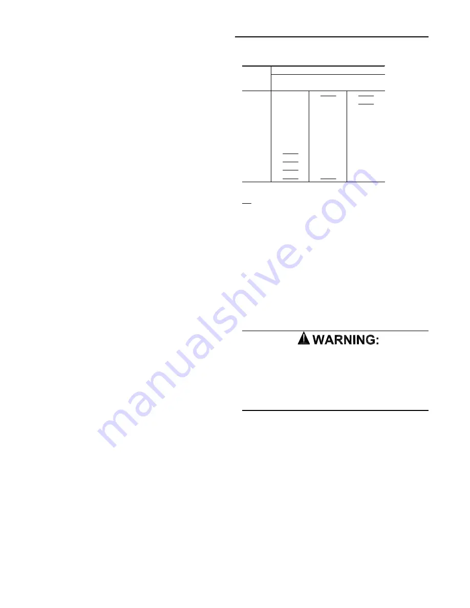
Table 5-1
EVP GPM vs Pressure Drop
Chiller Pressure Drop **
GPM* Chiller Size
80 Ton
100 Ton
120 Ton
100
4.5
120
6.5
3.2
140
8.7
4.3
3.2
160
11.2
5.6
4.1
180
14.1
7.0
5.2
200
17.2
8.5
6.3
240
24.8
12.2
9.0
280
16.3
12.0
320
21.0
15.8
360
26.0
19.7
400
24.0
* - Gallons Per Minute
** - All Pressure Drops are in Feet of Water
= Beyond the working limits of the barrel
“Air Over” Evaporator Application
Verifying Proper Supply Fan Rotation
1. Ensure that the “System” selection switch at the remote
panel is in the “Off” position and the “Fan” selection
switch for the appropriate controls application is in the
“Auto” position. (VAV units do not utilize a “Fan” selection
input.)
2. Turn the main power disconnect switch or circuit protec-
tor switch for the unit to the “On” position.
3. Turn the 115 volt control circuit switch 1S2 to the “On”
position.
HAZ A R D O U S V O L TA G E
R O T A T I N G P A R T S !
UNIT STARTS AUTOMATICALLY
Make sure all personnel are standing clear of the unit
before proceeding. The system components will start
when the power is applied.
4. Turn the field provided disconnect switch for the supply
fan to the “On” position and “bump” the field supplied
control circuit switch “On”, (i.e., “On” then immediately
“Off”).
5. While the fan is coasting down, check the rotation. If the
fan is rotating backwards, turn the field provided discon-
nect switch for the air handler to the “Off” position and in-
terchange any two of the main power wires at the fan
motor starter or contactor.
6. After all adjustments have been made, restart the supply
fan and proceed through the following procedures.
System Start-Up (Continued)
Summary of Contents for RAUC-IOM-15
Page 8: ...8 Figure 3 2A RAUC C80 Unit Dimensional Data Recommended Clearances...
Page 9: ...9 Figure 3 2A Continued RAUC D10 Unit Dimensional Data Recommended Clearances...
Page 10: ...10 Figure 3 2A Continued RAUC D12 Unit Dimensional Data Recommended Clearances...
Page 11: ...11 Figure 3 2B EVPB C80 Evaporator Chiller Dimensions...
Page 12: ...12 Figure 3 2B Continued EVPB D10 Evaporator Chiller Dimensions...
Page 13: ...13 Figure 3 2B Continued EVPB D12 Evaporator Chiller Dimensions...
Page 14: ...14 Figure 3 2B Continued EVPB C80 through D12 Chill Water Pipe Stubout Dimensions...
Page 35: ...35 Installation Continued Field Connection Diagram Notes for all System Control Options...
Page 57: ...57 Figure 5 5 Typical Scroll Compressor Terminal Block System Start Up Continued...
Page 67: ...67...
Page 68: ...68...


