28
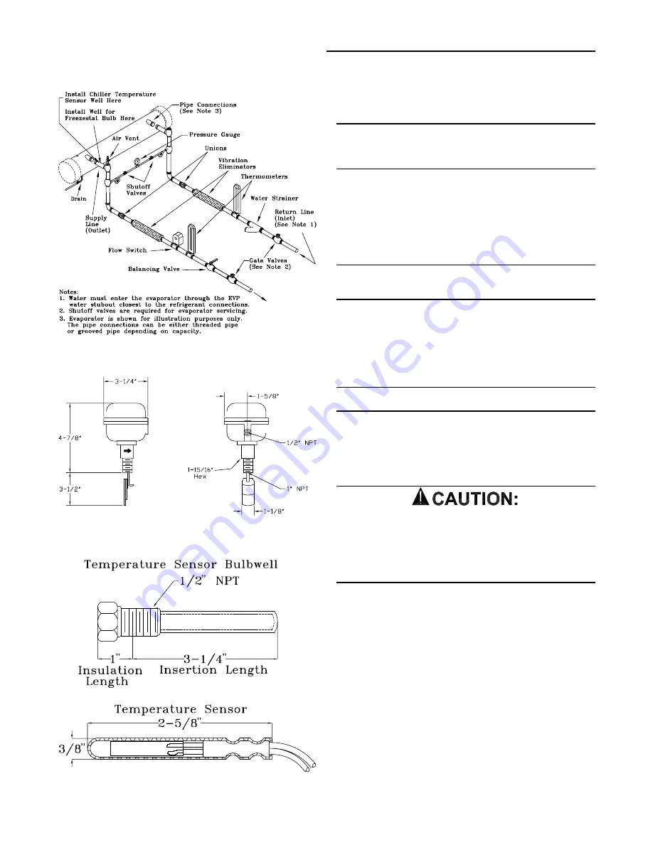
Figure 3-8
Typical Piping Recommendations
Figure 3-9
Optional Flow Switch Illustration
Figure 3-10
Temperature Sensor & Well
Final Water Piping Connections
1. All water piping to the system should be flushed thor-
oughly before making the final connections.
Note: If an acidic commercial flushing solution is
used, construct a temporary bypass around the
EVP chiller barrel to prevent damage to the internal
components of the evaporator.
2. Connect the water pipe to the EVP chiller.
3. Install the drain plug, (if no drain is used) or ensure the
drain shutoff valve is closed.
4. While filling the chiller system with solution, vent the air
from the system at the highest points.
Note: To prevent possible damage to the
equipment, do not use untreated or improperly
treated water in the system.
Field Installed Power Wiring
An overall dimensional layout for the field installed wiring
entrance into the unit is illustrated in Figure 3-2. To insure
that the unit’s supply power wiring is properly sized and in-
stalled, follow the guidelines outlined below.
Note: All field installed wiring must conform to NEC
guidelines as well as State and Local codes.
Verify that the power supply available is compatible with the
unit’s nameplate ratings. The available supply power must
be within 10% of the rated voltage stamped on the name-
plate. Use only copper conductors to connect the 3-phase
power supply to the unit.
U S E C O P P E R C O N D U C T O R S O N L Y !
UNIT TERMINALS ARE NOT DESIGNED TO ACCEPT
OTHER TYPES OF CONDUCTORS.
Failure to do so may cause damage to the equip-
ment.
Main Unit Power Wiring
Table 3-4 lists the field connection wire ranges for the main
power terminal block 1TB1. The unit electrical data is listed
in Table 3-5. The electrical service must be protected from
over current and short circuit conditions in accordance with
NEC requirements. Protection devices must be sized ac-
cording to the electrical data on the nameplate. Refer to the
“Power Wire Sizing & Protection Device Equations”, for de-
termining;
a. the appropriate electrical service wire size based on
“Minimum Circuit Ampacity” (MCA),
b. the “Maximum Over current Protection” (MOP)
device.
c. the “Recommended Dual Element fuse size” (RDE).
Installation (Continued)
Summary of Contents for RAUC-IOM-15
Page 8: ...8 Figure 3 2A RAUC C80 Unit Dimensional Data Recommended Clearances...
Page 9: ...9 Figure 3 2A Continued RAUC D10 Unit Dimensional Data Recommended Clearances...
Page 10: ...10 Figure 3 2A Continued RAUC D12 Unit Dimensional Data Recommended Clearances...
Page 11: ...11 Figure 3 2B EVPB C80 Evaporator Chiller Dimensions...
Page 12: ...12 Figure 3 2B Continued EVPB D10 Evaporator Chiller Dimensions...
Page 13: ...13 Figure 3 2B Continued EVPB D12 Evaporator Chiller Dimensions...
Page 14: ...14 Figure 3 2B Continued EVPB C80 through D12 Chill Water Pipe Stubout Dimensions...
Page 35: ...35 Installation Continued Field Connection Diagram Notes for all System Control Options...
Page 57: ...57 Figure 5 5 Typical Scroll Compressor Terminal Block System Start Up Continued...
Page 67: ...67...
Page 68: ...68...


