


ECM Overview and Setup
42
UNT-SVX041D-EN
Adjusting Optional Auto-Changeover
Function on CSTI Units
The motor control board provides additional temperature
controlled logic to help coordinate certain electric-heat
and valve logic functions:
•
On units with electric heat and a changeover coil, the
motor control board and adapter boards are pre-
configured to cause hydronic heat and electric heat to
be mutually exclusive:
–
On units with BACnet® controls (UC400-B), the
Tracer® controller board will serve as the primary
logic to select the electric heat only if hot water is
not available, but the motor control board will
service as a backup lockout.
–
On units with Customer Supplied Controllers (CSTI
units), the motor control board and CSTI board will
serve as the primary lockout.
•
On CSTI units selected with a changeover coil
configuration, the motor control board is factory
configured to work in conjunction with the CSTI
adapter board to provide a useful auto-changeover
function. Traditionally, a fixed setpoint bi-metallic disc
temperature switch is used to provide changeover with
customer controls; however, the motor control board
has defeatable and configurable bi-metallic disc
temperature switch emulation when combined with
the CSTI adapter board. The motor control board is
pre-configured for typical values, so changeover
settings do not necessarily need to be changed.
Note:
CSTI board does not support changeover function
with modulating valves.
–
An NTC thermistor is supplied and affixed to the
supply pipes where applicable. The motor control
board has several settings that affect the operation
of the changeover function:
•
parameter should normally be set to
or
to use the changeover functions.
•
parameter should be chosen if the unit has
a changeover coil without electric heat.
•
parameter should be chosen if the unit
has a changeover coil with electric heat.
Generally, this will perform the same as the
parameter but in addition, will disable heating
function on electric heat and on the changeover
coil if there are fan failures. The auxiliary heating
coil function will continue to operate and
respond to the customer heating request.
•
parameter should be set to
for CSTI units and
to
for ComfortLink or BACnet controller units.
•
parameter defines the temperature at which the
motor control board will close the triac onboard the
motor control board (if
parameter is set
correctly).
•
parameter defines the temperature at which the
motor control board will open the triac onboard the
motor control board (if
parameter is set
correctly). By leaving a “gap” between the make and
break value, we will simulate hysteresis of a real bi-
metallic disc temperature switch.
•
When combined with the CSTI adapter board, the bi-
metallic disc temperature switch emulation and the
electric heat lockout function will work when the
switches are set correctly.
Configurations
Every Trane unit with ECM motors will have modules
specifically configured at the factory for the operation of
that unit. The motor control board configuration label is
affixed to the sheet metal panel that covers the fan/motor
(see
and
).
The serial number of each unit and the custom
configuration settings specific to that unit will be printed
on the label for convenient matching of labels/settings to
specific units. Programming a unit with the settings from
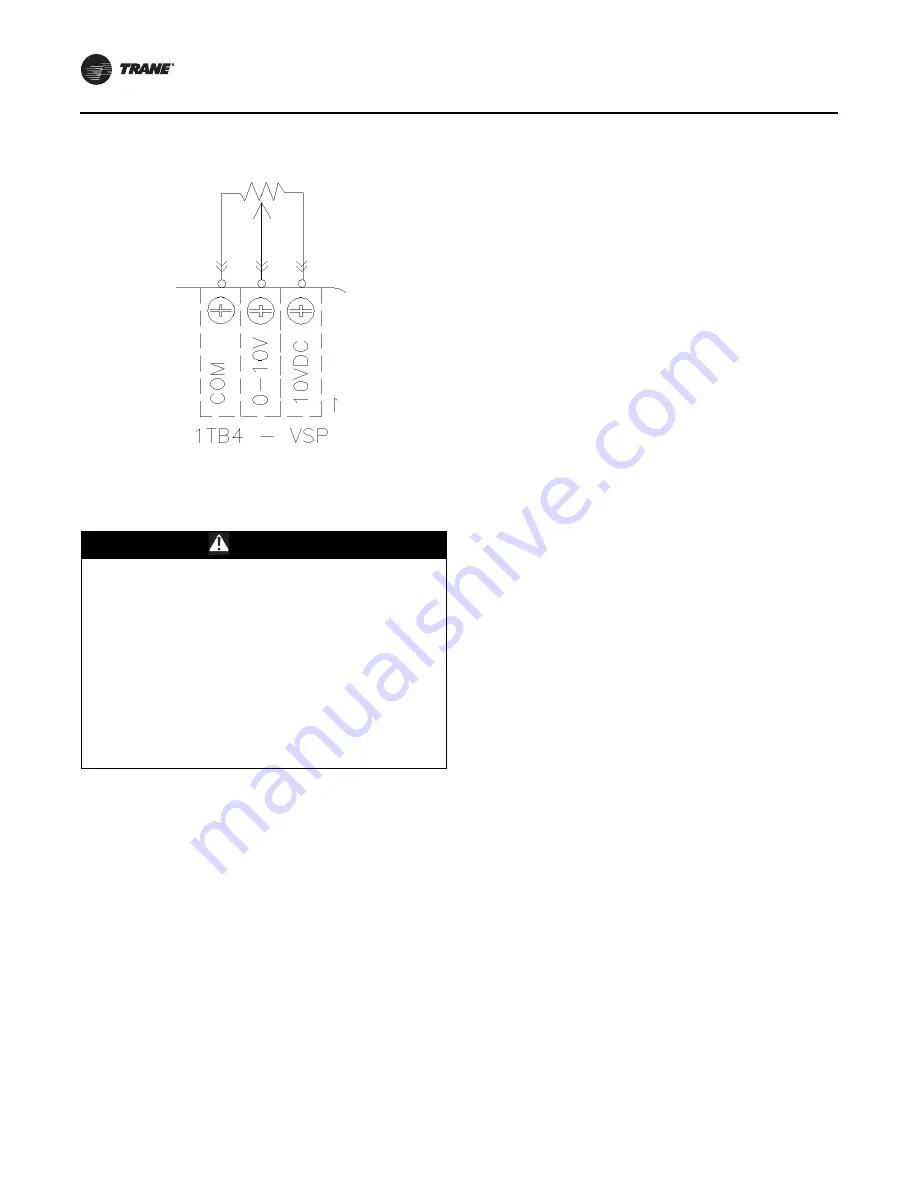
Figure 31.
Typical connection
WARNING
Hazardous Voltage w/Capacitors!
Failure to disconnect power and discharge capacitors
before servicing could result in death or serious injury.
Disconnect all electric power, including remote
disconnects and discharge all motor start/run
capacitors before servicing. Follow proper lockout/
tagout procedures to ensure the power cannot be
inadvertently energized. For variable frequency drives or
other energy storing components provided by Trane or
others, refer to the appropriate manufacturer’s literature
for allowable waiting periods for discharge of
capacitors. Verify with a CAT III or IV voltmeter rated per
NFPA 70E that all capacitors have discharged.


