


48
Quick control
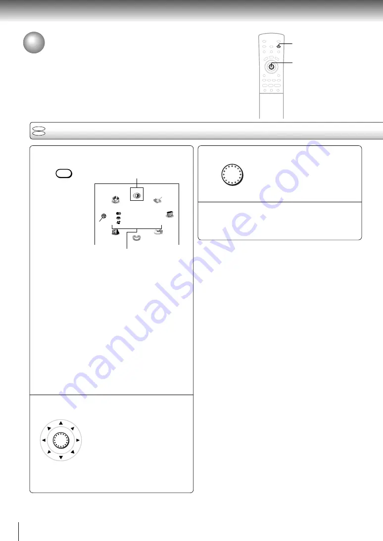
Accessing Features - NAVI -
The NAVI menu provides an icon based display from which you can easily
access key playback function.
NAVI menu items
Press NAVI.
The NAVI menu appears.
Each time you press the NAVI button, the display
changes.
Title/Chapter: Elapsed time and remainig time of
the current title/chapter.
Audio:
Current audio setting
Subtitle:
Current subtitle setting
Angle:
Current angle setting
Bit Rate:
Data transfer rate (Mbit/s)
Amount of picture, sound and
subtitle data in the DVD video disc
transferred per second.
The larger the value, the more data
processed, but this does not
necessarily insure better picture
quality.
Status display (playback mode, current DNR
setting, current zoom status, etc.)
Move the cursor control to select a
desired feature icon.
For details on each feature, refer to
the list on the next page.
1
2
Feature icon
ENTER
3
4
NAVI
Press ENTER.
Selection details appears.
Refer to the list on the next page and
follow the instructions detailed on
subsequent pages.
Notes
• The NAVI menu will disappear by pressing the NAVI button
several times.
• The number of feature icons on the display will vary
depending on the disc.
• Feature icons are displayed only when you play a DVD video
disc.
1
2, 3
ENTER
DVD
CD
Navi
Z M
V-Remote
Title:
Chapter:
Audio
Subtitle
Angle
Bit Rate:
Angle Viewer
Strobe Viewer
DNR
Preview
N-2-2
3D
Zoom
Capture
Summary of Contents for SD-2300
Page 1: ...DVD VIDEO PLAYER SERVICE MANUAL Feb 2001 S FILE NO 810 200019 SD 2300 ...
Page 5: ...SECTION 1 GENERAL DESCRIPTIONS 1 OPERATING INSTRUCTIONS SECTION 1 GENERAL DESCRIPTIONS ...
Page 20: ...16 Introduction ...
Page 28: ......
Page 29: ...Basic playback Begin your operation Playing a Disc Locating a Specific Title Chapter or Track ...
Page 36: ......
Page 48: ......
Page 58: ......
Page 71: ...Others Before Calling Service Personnel Specifications LIMITED WARRANTY DVD VIDEO PLAYER ...
Page 103: ...4 2 Power Supply Block Diagram Fig 3 4 2 ...
Page 105: ...Fig 3 4 5 4 3 3 Front Display Power Switch Block Diagram ...
Page 107: ...Fig 3 4 7 4 4 2 Logical System Block Diagram ...
Page 108: ...4 5 Output Block Diagram Fig 3 4 8 ...
Page 111: ...10 1 3 4 A B C D E G 2 5 6 7 8 9 F Fig 3 5 3 5 2 Front Display Power Switch Circuit Diagram ...
Page 119: ...Fig 3 5 5 5 3 2 Main Circuit 1 Diagram ...
Page 120: ...5 3 3 Main Circuit 2 Diagram Fig 3 5 6 ...
Page 121: ...5 3 2 Main Circuit 1 Diagram ...
Page 122: ......
Page 123: ......
Page 124: ......
Page 125: ......
Page 126: ......
Page 127: ......
Page 128: ...Fig 3 5 5 ...
Page 129: ...5 3 3 Main Circuit 2 Diagram ...
Page 130: ......
Page 131: ......
Page 132: ......
Page 133: ......
Page 134: ......
Page 135: ......
Page 136: ...Fig 3 5 6 ...
Page 139: ...10 1 3 4 A B C D E G 2 5 6 7 8 9 F Fig 3 5 7 5 4 Output Circuit Diagram ...
Page 160: ......


