


46
Quick control
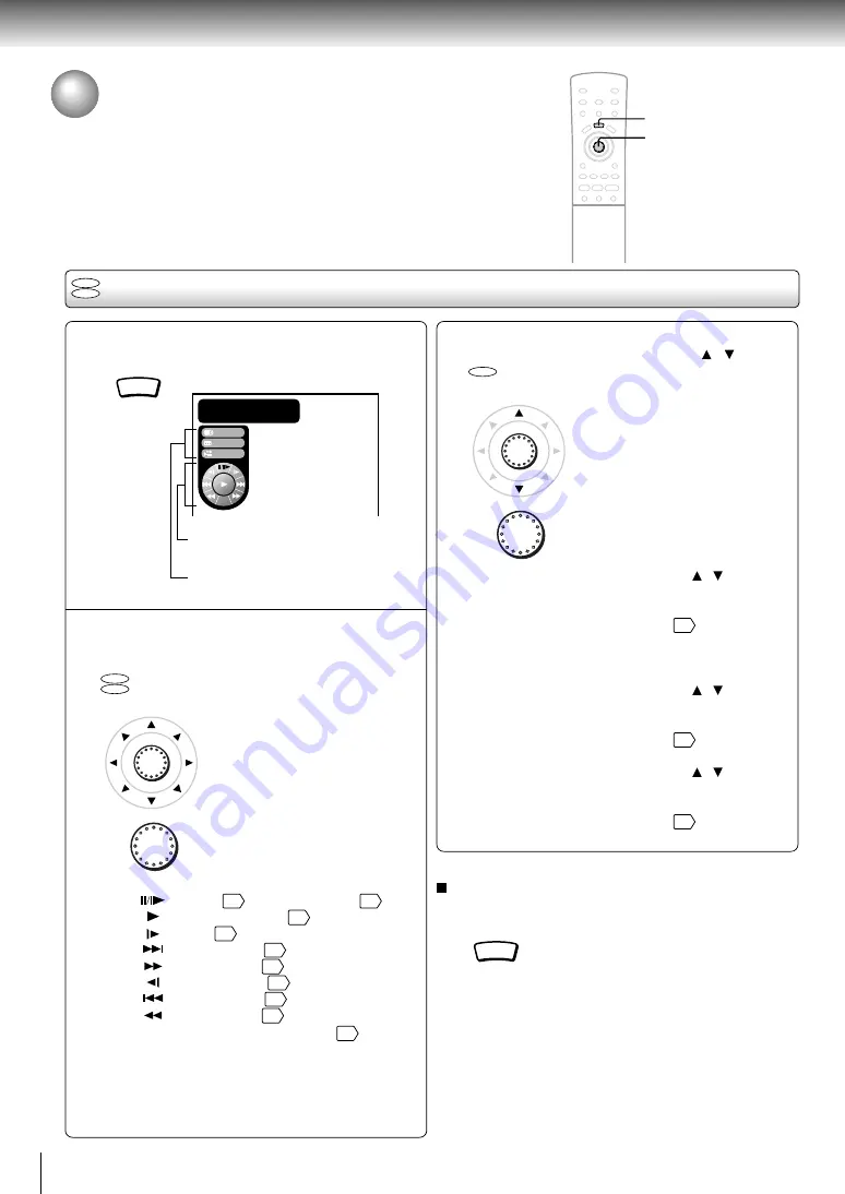
Using the Graphic Remote Control
- V-REMOTE -
Pressing one button can display a graphics based on-screen remote control that
allows you to control playback as if you were doing it from the actual remote
control.
During playback, press V-REMOTE.
The graphic remote control (Virtual
Remote) appears.
Proceed to A or B.
A
: Move the cursor control to select
the speed control, and press
ENTER.
: Pause
27
/ Frame by frame
28
: Normal playback
26
: Slow
29
: Forward skip
31
: Fast forward
28
: Reverse slow
29
: Reverse skip
31
: Fast reverse
28
Navi : Accesses the Navi menu
48
1
V-REMOTE
Using the graphic remote control
B
: Move the cursor control ( / ) to
select “Audio,” “Subtitle,” or
“Angle,” and press ENTER.
Audio:
Move the cursor control ( / ) to select
a desired audio language, and press
ENTER.
For details, see page
42
.
Selecting the output sound format is not
possible here.
Subtitle: Move the cursor control ( / ) to select
a desired subtitle language, and press
ENTER.
For details, see page
41
.
Angle:
Move the cursor control ( / ) to select
a desired camera angle, and press
ENTER.
For details, see page
40
.
To turn off the Virtual Remote
Press V-REMOTE.
Note
Some discs may not permit this operation.
V-REMOTE
2
DVD
CD
ENTER
ENTER
ENTER
ENTER
DVD
CD
DVD
Stream selection
Proceed to 2-B.
Speed control
Proceed to 2-A.
Audio
Subtitle
1
Title :
0 12 34
:
:
Angle
Navi
C
2
hapter :
0 01 23
:
:
2
1
Summary of Contents for SD-2300
Page 1: ...DVD VIDEO PLAYER SERVICE MANUAL Feb 2001 S FILE NO 810 200019 SD 2300 ...
Page 5: ...SECTION 1 GENERAL DESCRIPTIONS 1 OPERATING INSTRUCTIONS SECTION 1 GENERAL DESCRIPTIONS ...
Page 20: ...16 Introduction ...
Page 28: ......
Page 29: ...Basic playback Begin your operation Playing a Disc Locating a Specific Title Chapter or Track ...
Page 36: ......
Page 48: ......
Page 58: ......
Page 71: ...Others Before Calling Service Personnel Specifications LIMITED WARRANTY DVD VIDEO PLAYER ...
Page 103: ...4 2 Power Supply Block Diagram Fig 3 4 2 ...
Page 105: ...Fig 3 4 5 4 3 3 Front Display Power Switch Block Diagram ...
Page 107: ...Fig 3 4 7 4 4 2 Logical System Block Diagram ...
Page 108: ...4 5 Output Block Diagram Fig 3 4 8 ...
Page 111: ...10 1 3 4 A B C D E G 2 5 6 7 8 9 F Fig 3 5 3 5 2 Front Display Power Switch Circuit Diagram ...
Page 119: ...Fig 3 5 5 5 3 2 Main Circuit 1 Diagram ...
Page 120: ...5 3 3 Main Circuit 2 Diagram Fig 3 5 6 ...
Page 121: ...5 3 2 Main Circuit 1 Diagram ...
Page 122: ......
Page 123: ......
Page 124: ......
Page 125: ......
Page 126: ......
Page 127: ......
Page 128: ...Fig 3 5 5 ...
Page 129: ...5 3 3 Main Circuit 2 Diagram ...
Page 130: ......
Page 131: ......
Page 132: ......
Page 133: ......
Page 134: ......
Page 135: ......
Page 136: ...Fig 3 5 6 ...
Page 139: ...10 1 3 4 A B C D E G 2 5 6 7 8 9 F Fig 3 5 7 5 4 Output Circuit Diagram ...
Page 160: ......


