– 52 –
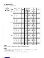
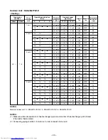
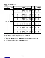
Table 8-1-2
NOTE :
• UL : Ultra Low, SUL : Super Ultra Low
Operation
mode
COOL
DRY
HEAT
FAN
mode
H
M+
M
L
L–
UL
SUL
L–
SUL
H
M+
M
L
L–
UL
SUL
M10
Motor speed
Air flow rate
(rpm)
(m³/h)
1100
470
1100
470
1010
440
910
380
810
320
770
300
760
300
810
320
760
300
1200
520
1200
520
1100
470
930
390
930
390
810
320
670
260
M13
Motor speed
Air flow rate
(rpm)
(m³/h)
1200
520
1140
510
1050
470
910
380
820
330
770
300
760
300
820
330
760
300
1280
560
1280
560
1100
470
930
390
930
390
820
330
730
290
M16
Motor speed
Air flow rate
(rpm)
(m³/h)
1350
600
1300
580
1190
520
980
420
920
380
870
360
820
330
920
380
820
330
1350
600
1350
600
1200
520
980
420
980
420
920
380
730
290
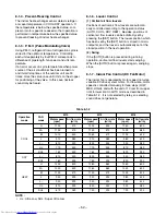
8-1-6. Louver Control
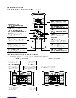
(1) Vertical air flow louvers
Positions of vertical air flow louvers are automati-
cally controlled according to the operation status
(AUTO, COOL, DRY, HEAT). Besides, positions of
vertical air flow louvers can be arbitrarily set by
pressing the [SET] button. The louver position which
has been set by the [SET] button is stored in micro-
computer, and the louver is automatically set at the
stored position in the next operation.
(2) Swing
If the [AUTO] button is pressed during running
operation, vertical air flow louvers start swinging.
When the [AUTO] button is pressed again, swinging
stops.
8-1-7. Indoor Fan Control (DC Fan Motor)
The indoor fan is operated by motor speed non-step
variable DC drive system motor. For flow rate, motor
speed is controlled manually in three steps (LOW,
MED, HIGH), and with the unit of 10 rpm from upper
limit to lower limit in AUTO mode as described in
Table 8-1-2. It is not selected by relay, so selecting
sound does not generate.
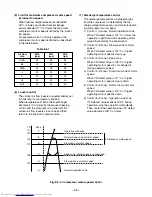
8-1-4. Prevent-Freezing Control
The indoor heat exchanger sensor detects refriger-
ant vapor temperature in COOL/DRY operation. If
the temperature is below the specified value, com-
pressor motor speed is reduced so that operation is
performed in temperature below the specified value
to prevent-freezing of indoor heat exchanger.
8-1-5. P. M. V. (Pulse Modulating Valve)
Using P.M.V., refrigerant flow of refrigeration cycle is
varied for the optimum temperature. Controlling
each unit separately by four P.M.V. corresponds to
difference of pipe length, fan speed, and unit tem-
perature.
If an error occurs on cycle temperature when power
source of the air conditioner has been turned on,
and if start/stop times of the outdoor unit are 30
times, move the valve once until it hits on the stopper
for positioning of the valve. In this case, ticktack
sound may be heard.


