


Error! Style not defined. Error! Style not defined.
4 Replacement Procedures
4.1
General
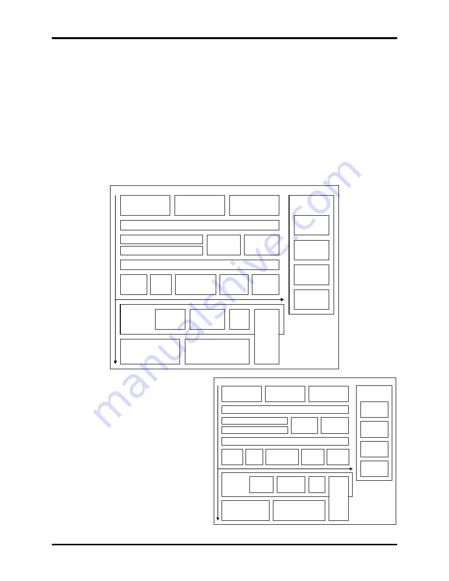
This chapter explains how to disassemble the computer and replace Field Replaceable Units
(FRUs). Some replacement procedures may not require you to remove all the surrounding FRUs
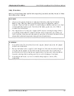
to replace only one FRU. The chart below shows the FRUs in the order in which they should be
removed in a top-down manner, irrespective of their physical locations. The FRUs shown in the
top area of the chart should normally be removed before removing the FRUs shown in the
bottom area. To replace the FRUs, first identify the suspect FRU for the system failure. Next,
according to this chart, determine the FRUs that need to be removed before removing the suspect
FRU. After you determine those FRUs, go to the appropriate sections according to the section
numbers shown in the boxes. Then start removal and replacement.
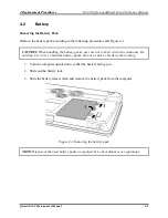
4.2
Battery
4.3
HDD
4.4
Memory
4.5 Keyboard Cover & Keyboard
4.8 Express
Dummy Card
4.6 Wireless LAN Card and UWB Card
4.7 ODD
4.10 Top Cover
4.12 DC-in
jack
4.14 Touch Pad &
Finger Print Board
4.15 Power
Switch
4.16 Audio
Card
4.17 MDC
Module &
System Board
4.18 VGA
Module
4.19 Cooling
Module & Fan
4.11
Display Assembly
4.20
CPU
4.24
Display Mask
4.25 FL
Inverter Board
4.26
CCD & MIC
4.27 LCD
Modules
4.21
Sub-speakers
& Sub-woofer
4.22
Bluetooth, Wi-Fi, Touch Pad
LED Board
4.23
Bridge
Media &
FM
Radio
4.9 Optional
Memory Card
4.13
Speaker
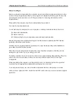
How to use the chart (two examples):
4.2
Battery
4.3
HDD
4.4
Memory
Qosmio X300 Maintenance Manual
4-1
•
For removing the System Board:
First, remove the top cover with the
display assembly. Then, remove the
HDD, selectable bay module, Bluetooth
card, keyboard, and wireless LAN card,
all of which are shown above the top
cover with the display assembly.
•
For removing the LCD Module:
First, remove the display mask and FL
inverter board, both of which are shown
above the LCD module.
4.5 Keyboard Cover & Keyboard
4.8 Express
Dummy Card
4.6 Wireless LAN Card and UWB Card
4.7 ODD
4.10 Top Cover
4.12 DC-in
jack
4.14 Touch Pad &
Finger Print Board
4.15 Power
Switch
4.16 Audio
Card
4.17 MDC
Module &
System Board
4.18 VGA
Module
4.19 Cooling
Module & Fan
4.11
Display Assembly
4.20
CPU
4.24
Display Mask
4.25 FL
Inverter Board
4.26
CCD & MIC
4.27 LCD
Modules
4.21
Sub-speakers
& Sub-woofer
4.22
Bluetooth, Wi-Fi, Touch Pad
LED Board
4.23
Bridge
Media &
FM
Radio
4.9 Optional
Memory Card
4.13
Speaker
Summary of Contents for Qosmio X300 Series
Page 1: ...Toshiba Personal Computer Qosmio X300 Maintenance Manual TOSHIBA CORPORATION CONFIDENTIAL ...
Page 10: ...Chapter 1 Hardware Overview ...
Page 11: ...1 Hardware Overview Qosmio X300 Maintenance Manual 1 ii ...
Page 31: ...Chapter 2 Troubleshooting Procedures 2 ...
Page 32: ......
Page 99: ...3 Tests and Diagnostics 1 Chapter 3 Tests and Diagnostics ...
Page 104: ...3 Tests and Diagnostics 6 ...
Page 115: ...3 Tests and Diagnostics Japan keyboard UK keyboard 17 ...
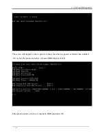
Page 128: ...3 Tests and Diagnostics If the picture shows as below it means he HDD function is NG 30 ...
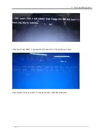
Page 136: ...3 Tests and Diagnostics You can press ESC to exit test after test pass 38 ...
Page 137: ...Chapter 4 Replacement Procedures ...
Page 138: ...4 Replacement Procedures Qosmio X300 Maintenance Manual 4 ii ...
Page 144: ...4 Replacement Procedures Qosmio X300 Maintenance Manual 4 viii ...


