User’s Manual
33
PART 1 AD268
7. Troubleshooting
7.2 Troubleshooting
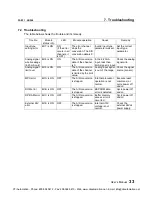
The table below shows the trouble and its remedy.
Trouble
Module
status info
LED
Module operation
Cause
Remedy
Input type
setting error
Bit 7 is ON
ON
(if the error
occurs in all
channels, it
is OFF)
The error channel
stops the
conversion. The A/D
conversion data is 0.
Invalid input type
parameter was set.
Set the correct
input type
parameter.
Analog signal
wire breakage
(4-20mA only)
Bit 8 is ON
ON
The A/D conversion
data of the channel
is 0.
In the 4-20mA
input, less than
4mA signal is input.
Check the analog
signal wire.
Analog signal
limit over
Bit 9 is ON
ON
The A/D conversion
data of the channel
is limited by the limit
value.
Analog input signal
is out of the range.
Check the signal
source (sensor).
MPU error
Bit A is ON
OFF
The A/D conversion
is stopped.
Internal processor
operation is not
normal.
Execute reset
command, or
cycle power off
and on.
ROM error
Bit B is ON
OFF
The A/D conversion
is stopped.
EEPROM data
error is detected.
Cycle power off
and on.
DP-RAM error Bit C is ON
OFF
The A/D conversion
is stopped.
Buffer memory
access error is
occurred.
Cycle power off
and on.
External 24V
error
Bit E is ON
OFF
The A/D conversion
is stopped.
Internal
±
15V
voltage is not
normal.
Check the
external 24Vdc
power supply.
CTi Automation - Phone: 800.894.0412 - Fax: 208.368.0415 - Web: www.ctiautomation.net - Email: [email protected]


