16
Analog I/O Modules (AD268 / DA264 / TC218)
4. Wiring
PART 1 AD268
4.3 Wiring precautions
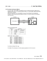
(1) Use shielded twisted-pair cables for analog input signal lines and wire them in shortest
distance. Connect the cable shield to ground in shortest distance for EMC conformity.
Normally the grounding method (a) is recommended. However, depending on the condition,
method (b) or (c) may be useful for stable operation.
(2) Separate the analog signal cable from other cables to prevent noise interference. (200mm
or more)
(3) This module requires 24Vdc power. Apply the 24Vdc power before (or at the same time)
applying T2’s main power. Otherwise, this module detects the external 24Vdc error.
(4) If the external 24Vdc power for this module is not stable, the converted data will not be
stable. In this case, use a dedicated 24Vdc power supply for this module.
(5) It is recommended to short the unused channels. Because if it is open for voltage input,
meaningless A/D conversion data will appear.
(6) If the converted data is not stable owing to electrical noise, it is recommended to use the
input averaging function to reduce the noise interference. For the averaging function, refer
to section 6.
Analog input
module
FG
(a)
Analog input
module
FG
(b)
Analog input
module
FG
(c)
CTi Automation - Phone: 800.894.0412 - Fax: 208.368.0415 - Web: www.ctiautomation.net - Email: [email protected]

