


18
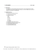
Analog I/O Modules (AD268 / DA264 / TC218)
5. I/O Allocation and Programming
PART 1 AD268
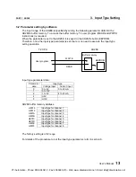
5.2 A/D conversion data
The analog signals received by the AD268 are converted into the digital data in this module.
These converted digital data are read by T2 CPU in the batch I/O processing and stored in the
assigned input registers as follows.
XW(n) ........ A/D conversion data for channel 1
XW(n+1) .... A/D conversion data for channel 2
XW(n+2) .... A/D conversion data for channel 3
XW(n+3) .... A/D conversion data for channel 4
XW(n+4) .... A/D conversion data for channel 5
XW(n+5) .... A/D conversion data for channel 6
XW(n+6) .... A/D conversion data for channel 7
XW(n+7) .... A/D conversion data for channel 8
The conversion data stored in the XW register is dependent on the input type as follows.
±±±±
10V range:
A/D conversion data
Input voltage
Hexadecimal
Integer
Resolution
Upper limit
+10.2 V
H7F80
32640
:
:
:
Full scale (positive)
+10 V
H7D00
32000
:
:
:
+0.3125 mV
H0001
1
0
0 V
H0000
0
-0.3125 mV
HFFFF
-1
:
:
:
Full scale (negative)
-10 V
H8300
-32000
:
:
:
Lower limit
-10.2 V
H8080
-32640
0.3125 mV / bit
+10.2V
HC000
-16384
0
H3FFF
16383
+10V
H7D00
32000
+5.1196V
-5.12V
-10.2V
-10V
H8300
-32000
Digital value
Analog input
D = 3200
×
A
D: Digital data
A: Analog signal (V)
CTi Automation - Phone: 800.894.0412 - Fax: 208.368.0415 - Web: www.ctiautomation.net - Email: [email protected]


