12
Analog I/O Modules (AD268 / DA264 / TC218)
3. Input Type Setting
PART 1 AD268
3. Input Type Setting
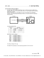
The AD268 supports multiple input ranges,
±
5V,
±
10V, 0 to 5V, 0 to 10V, 1 to 5V, 0 to 20mA,
or 4 to 20mA. The input range is selected by jumper plug setting and the parameter writing by
the T2 program.
The general flow for setting the input type is as follows.
(1) Set the jumper plugs to select voltage input or current input.
(2) Mount the AD268 onto the T2 rack.
(3) Turn on power to the T2 system.
(4) Execute I/O allocation.
(5) Program the "input type setting program". (see the next page)
(6) Turn the T2 to RUN mode.
3.1 Jumper plug setting
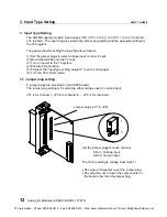
8 jumper plugs are provided on the AD268 board.
The jumper plug setting is for selecting either voltage input or current input.
JP1 is for channel 1, JP2 is for channel 2, ... JP8 is for channel 8.
Jumper plugs (JP1 to JP8)
1
3
Set the jumper plugs for each channel.
Side 1: Voltage input
Side 3: Current input
The factory setting is voltage input (side 1).
•
Use a pair of tweezers to set the jumper plug.
•
Pay attention not to touch the components on
the board other than the jumper plug.
CTi Automation - Phone: 800.894.0412 - Fax: 208.368.0415 - Web: www.ctiautomation.net - Email: [email protected]

