User’s Manual
29
PART 1 AD268
6. Parameters
Analog input actual value:
(H8028 to H802F)
These data show the original A/D conversion data before processing the gain and offset
calibration.
Module status:
(H8030 to H8037)
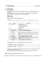
These data show the AD268’s operation status.
Bit position
→
F
E
D
C
B
A
9
8
7
6
5
4
3
2
1
0
0
0
0
0
Bit
Name
Description
0 to 2
Input type
Shows the input type.
000 (0) = 0 to 5V/0 to 20mA
001 (1) = 0 to 10V
010 (2) = 1 to 5V/4 to 20mA
100 (4) =
±
5V
101 (5) =
±
10V
3 to 5
-
Reserved
6
Channel skip
1 when the channel skip is designated.
7
Input type setting
error
1 when the input type designation is invalid.
8
Wire break
1 when wire breakage is detected. (Effective only for 4 to 20mA
input)
9
Input limit
1 when the A/D conversion data is limited because of the range
over.
A
MPU error
1 when the AD268’s processor is not normal.
B
ROM status
1 when the AD268’s EEPROM is not normal.
C
DP-RAM status
1 when the AD268’s DP-RAM (buffer memory) is not normal.
D
-
Reserved
E
External 24V error
1 when the external 24Vdc is not normal.
F
Initializing
1 during the AD268 is in initialization process.
CTi Automation - Phone: 800.894.0412 - Fax: 208.368.0415 - Web: www.ctiautomation.net - Email: [email protected]


