background image

6.  Time Monitoring

37

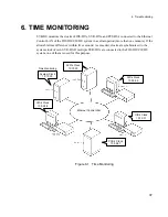
6. TIME MONITORING

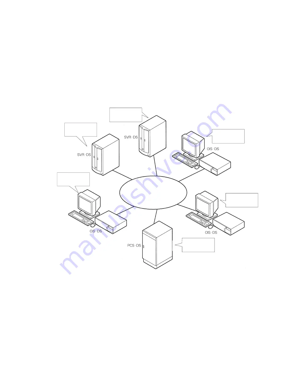
SVR-DS monitors the clocks of OIS-DS

s, SVR-DS

s, and PCS-DS

s connected to the Ethernet

Control LAN of the TOSDIC-CIE DS system in a certain period (more than one munute). If the

allowable time difference (within five seconds) is exceeded, clocks are synchronized to the

system clock of own SVR-DS. If multiple SVR-DS

s are connected to the TOSDIC-CIE DS

system, one of them is used for this purpose.

Ethernet Control LAN

Time Monitoring

System Clock

10:10:00

SVR’s Clock

10:10:00

OIS’s Clock

10:09:58

PCS’s Clock

10:09:57

OIS’s Clock

10:10:01

OIS’s Clock

10:09:59

Figure 6.1   Time Monitoring

Summary of Contents for 6F8C0791

Page 1: ...SVR DS System Function Manual 6F8C0791 Toshiba Integrated Control System MENU ...

Page 2: ... Edition July 1999 The contents of this manual may be revised without notice Copyright 1998 by Toshiba Corporation All rights reserved No part of this manual may be reproduced in any form without permission ...

Page 3: ...s Following shapes and symbols are used in the safety precaution labels affixed to the products and in other places including operation manuals for giving safety instructions Filled circle means Mandatory Action or Do as indicated Required action is shown in the circle or described near the circle Circle band with a diagonal slash means Prohibition or You must not do Prohibited action is shown in ...

Page 4: ...Location where the humidity exceeds the specified limits for installation l Location in the direct sunlight l Location near a device that generates strong radio waves or magnetic fields Considerations for maintenance and inspection Install the equipment in a place that facilitates maintenance and inspection If not in case of malfunctioning it may hinder the recovery of the system and result in ser...

Page 5: ...the equipment or modules to avoid fault Shocks may cause malfunction Discharge static electricity Before handling equipment or modules discharge static electricity from your body by touching a metal that is grounded Static electricity may cause equipment to malfunction or fail Use a conductive sheet or bag to avoid static When cards and modules are taken out of base unit they should be placed on a...

Page 6: ... not use the lithium battery in one module for another Ratings of lithium battery differs by the module and the use of improper battery may damage the equipment 4 Safety Precautions for Daily Use WARNING Check specifications Before using the equipment make sure that the capacity frequency voltage and regulation of the power supply meet the specifications of the equipment In case they don t the equ...

Page 7: ...tem is running Do not change function settings of switches on modules while the equipment is running Otherwise equipment may malfunction or fail Keep off metals Keep metals such as paper clips from going into the openings in the modules units and drives among others Otherwise fire may result 5 Safety Precautions for Disposal WARNING Keep lithium batteries out of fire To avoid risk of explosion do ...

Page 8: ...or use in a system containing equipment which directly involves human life Please see NOTE 1 This product must not be used for such uses l In case this product is to be used in a system see NOTE 2 containing equipment which involves human safety and may potentially cause serious impacts on the maintenance of public functions special considerations see NOTE 3 will be needed for system operation mai...

Page 9: ...nability to use this product including losses of business profits suspension of business and mutilation or erasure of stored data l Toshiba will not be responsible for damage caused due to a failure in complying with the content of this reference manual l Toshiba will not be responsible for damage caused by malfunctioning due to combination with equipment connected l Toshiba will not be responsibl...

Page 10: ...Safety Precautions viii ...

Page 11: ...irst read Safety Precautions carefully to use this device safely and correctly nComposition of This Functional Manual This manual consists of the following chapters Chapter 1 Overview of SVR DS This chapter describes the TOSDIC CIE DS system and SVR DS hardware configuration and standard functions Chapter 2 Tag Management This chapter describes the System Builder managed by SVR DS and the internal...

Page 12: ...ated Manuals There are the following related manuals for SVR DS ŸOIS DS System Overview Manual ŸOIS DS51 System Function Manual ŸSVR DS51 Hardware Instruction Manual nNotational Convention Other than the safety precautions this manual uses the following symbols to indicate items you need to be careful about when you use this product INSTRUCTION Describes items you need to perform to use this produ...

Page 13: ...l Tags 7 3 Database Management 9 Historical Database 10 Historical Tag 11 Redundancy of Historical Database 11 History Message 12 Report Database 13 Report Data Processing 15 Network Database 22 4 Background Processing 23 Alarm Monitoring 23 Process Alarms 23 System Alarms 27 Event Condition Management 28 Message Printing 29 Guidance Management 30 Internal Process Processing Signals 31 Redundant S...

Page 14: ...larm Output 35 6 Time Monitoring 37 7 User Application Environment 39 Data Sharing 40 RAS Functions 40 8 SVR Engineering 41 9 RAS Functions 43 RAS Information Collected 43 Alarm Display 43 Remote Diagnosis 44 Appendix1 System Specification of OIS DS SVR DS 45 ...

Page 15: ...em and SVR DS For TOSDIC CIE DS the maximum of two SVR DS stations eight OIS DS stations and 22 PCS DS stations can be connected to one system of Ethernet Control LAN OIS Engineering Tools general purpose workstations and PC s can be connected to the Information System Ethernet In the Ethernet Control LAN transmission lines can be made redundant SVR DS Workstation PC OIS DS OIS DS OIS SVR Engineer...

Page 16: ...onnected via the Ethernet Control LAN You can connect a printer for messages to SVR DS and a printer for reports and hard copies to OIS DS Voice Output Device Centronics SVR DS HUB HUB 10BASE T Control LAN 10BASE 5 Thick Wire Ethernet Trunk Line OIS DS RS 232C Touch Panel Centronics Black white Hard Copy Terminator Terminator Figure 1 2 Basic Configuration of OIS SVR ...

Page 17: ...B HUB 10BASE T Control LAN 10BASE 5 Thick Wire Ethernet Trunk Line OIS DS RS 232C Touch Panel Centronics Transceiver Cable Terminator Terminator OIS DS RS 232C Touch Panel Information System LAN Centronics Print Server Print Server Print Server For Reports For Hard Copies For History Messages Note Note Use the dedicated printer as a history message printer Figure 1 3 Connections of Shared Peripher...

Page 18: ...erver Print Server Centronics Centro nics For History Messages Note For Reports For Hard Copies Transceiver Cable Transceiver Transceiver Transceiver Transceiver Control LAN 10BASE 5 Thick Wire Ethernet Trunk Line B Control LAN 10BASE 5 Thick Wire Ethernet Trunk Line B Note Use the dedicated printer as a history message printer Figure 1 4 Connections for OIS SVR in a Redundant Transmission System ...

Page 19: ...internal tags System State Display Station State Display I O Card State Display System Alarm Monitoring including LAN monitoring LAN Statistics Information Version Display RAS Information Collection Guidance Monitoring Guidance Display Voice Message Output Trend Function Trend Display Process Alarm System Alarm Action Record Operation Record History Display Printing Message Function Connection wit...

Page 20: ...t Event Management Alarm Caching Alarm Management History Information Save Output to Peripheral Devices Voice Output Message Printing External Alarm O SVR Configuration Engineering Figure 1 6 Standard Functions of SVR DS OIS Functions during SVR System Down When SVR DS is down the following functions of OIS DS are restricted Ÿ History Save Display Ÿ Trend Save Display Ÿ Guidance Monitor Display Ÿ ...

Page 21: ...ags SVR DS manages parameters of OIS DS SVR DS and PCS DS data regarding OIS DS SVR DS guidance and process data for applications as internal tags Table 2 1 The List of Internal Tags Tag Type Description OIS Parameter Tags for management of OIS s parameters Process Tags for performing linerization process and industrial unit conversion of data of application programs or computers to manage it as p...

Page 22: ...2 Tag Management 8 ...

Page 23: ... processes and saves it as historical tag data You can write in or read out data It also collects event information of processes and the system and saves it as historical messages You can read and print out historical messages 2 Report Database Processes historical tag data in the Historical Database and saves it as report data You can write in or read out data 3 Network Database Saves historical ...

Page 24: ...creen display žTrend display žHistory message display User applications Reports žMaintenance ž Printing Historical tag setup žPCS tag number žSave period number of samples žArchive group žReport data processing History Message Tag Data Figure 3 2 Data Processing of Historical Database After its storage period is passed the historical tag data will be deleted from the historical database The histor...

Page 25: ...l l l lHistorical Tag Historical trend data history messages and report data are managed for each historical tag A maximum of 5 000 historical tags can be set up in the SVR DS Historical tags are set up each with a historical tag name tag number atom name collection period save period and other information Archive groups can also be set up Those historical tags used in the report function are set ...

Page 26: ...cal database of the SVR DS History data can be tracked in all the SVR DS units Histories Ethernet OIS DS SVR DS History Messages History Get Request Response Figure3 3 History Saving The following event record messages are saved Ÿ Process alarms Generation and recovery of process alarms Ÿ System alarms Generation and recovery of system alarms Ÿ Action records DI DO signal changes of digital tags Ÿ...

Page 27: ...d and is saved in individual report tags When report data is altered other report data calculated from this altered data is recalculated Data of the report database can be written and read using the historical tag access interface OIS DS Report Interface Read Change Report Window Excel Printing Function Maintenance Function Saving Historical Tag Interface SVR DS Report Database Report Tag Hourly D...

Page 28: ...inute Collection Points 5 000 tags system total with historical tags Save Period Hourly data Bimonthly quarterly and every 4 months Daily data Bimonthly quarterly and every 4 months Monthly data Every 2 3 and 4 years Yearly data Every 2 3 and 4 years Report Calculations of Collected Data Instantaneous maximum minimum and average values Maximum value time minimum value time and integrated values Co...

Page 29: ...elected and performed in accordance with the data processing system set up in the report database 1 Minutely system The day maximum value day maximum value time day minimum value day minimum value time and day average value for one day 60 x 24 samples of historical tag data collected in one minute periods are calculated and the calculation results are saved with report tags as daily data 2 Hourly ...

Page 30: ... monthly data 4 Yearly data One of the three systems namely minutely hourly maximum and hourly average systems is selected and performed in accordance with the data processing system set up in the report database 1 Minutely system The year maximum value year maximum value time year minimum value year minimum value time and year average value for one year 12 samples of month maximum value month min...

Page 31: ...nuary 12 Month Maximum Value Minimum Value Average Value First Day 31 Day Maximum Value Minimum Value Average Value Daily Data Monthly Data Yearly Data Minutely System Hourly Maximum System Hourly Average System Year Maximum Value Minimum Value Average Value Hourly Data January 12 Month Maximum Value Minimum Value Average Value First Day 31 Day Maximum Value Minimum Value Average Value Daily Data ...

Page 32: ...absolute value calculation system for each tag in accordance with the data processing system set up in the report database 1 Set phase calculation system The minimum value on the or side of a phase is set up as the minimum value of the phase 2 Absolute value calculation system The minimum value of an absolute value is set up as the minimum value of the absolute value 3 Average value The average va...

Page 33: ...tal tag signals is integrated 2 Daily data The day maximum value day maximum value time day minimum value day minimum value time day average value and day total value for one day 24 samples of hourly data are calculated and the calculation results are saved with report tags as daily data 3 Monthly data The month maximum value month maximum value time month minimum value month minimum value time mo...

Page 34: ...ata collected in one minute periods within one hour is invalid In the following events historical tag data is treated invalid Ÿ A readout error of tag number and atom name Ÿ Historical tag data exceeding the maximum tolerable value of the integrating meter or historical tag data with a minus value is collected from an integrating meter tag Ÿ An event condition is not established when an event cond...

Page 35: ... set them with report tags 1 Closing time Last time of one day to calculate daily data for one day Set between 1 and 24 hours in increments of one hour 2 Closing day Last day of one month to calculate monthly data for one month Set between 1 and 31 days in increments of one day 3 Closing month Last month of one year to calculate yearly data for one year Set between January and December in incremen...

Page 36: ...ication data files to save application data Data is equalized in the network databases of all the SVR DS units OIS DS SVR DS SVR Database Server Process User Applications Database Equalization SVR DS SVR Database Database Equalization The operator window is read from any SVR database The operator window is written in the SVR databases of all nodes ƒ The server process user applications etc are rea...

Page 37: ...ation Methods You can specify one method from Type A Type B and Type C for each tag Type A This type requires the display return operation When a signal is recovered and you perform a confirmation operation flashing stops The alarm remains displayed until you perform the display return operation Type B This type displays alarms that correspond to process states When a signal is recovered the uncon...

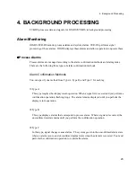
Page 38: ...lor Alarm Occurrence Alarm Confirmation Alarm Recovery Alarm Recovery by LO Key Operation after Signal Operation Note The LO key operation not confirmed is ignored ON MES AWOFF ON MES LO CNF Occurrence Recovery Not Confirmed Confirmed A A Ignored Signal OIS Status CRT Display Alarm Confirmation Operation LO Note AWON AD ALM ON Color OFF Color OFF ON Blinking ON OFF Operation Description Normal Ala...

Page 39: ...es in ON Color Note Alarm Occurrence Alarm Confirmation Alarm Recovery Recovery Message for Auto Recovery CRT Display recovers at Auto Recovery or at Alarm Confirmation Operation whichever occurs later ON MES AWOFF ON MES CNF Recovery Message Output OFF MES OFF MES Note Turns to OFF Color when the CNF key operation is performed first after signal recovery Occurrence Recovery Not Confirmed Confirme...

Page 40: ...ry Message Output and Alarm Output ON MES AWOFF ON MES CNF Recovery Message Output OFF MES OFF MES Note Turns to OFF Color when the CNF key operation is performed first after signal recovery CNF Not Confirmed OFF AWOFF Alarm Recovery Confirmation Alarm Recovery Confirmed AWON AD ALM Figure 4 3 A Type C Alarm There are the following alarm grades Table 4 1 Display Priorities for Process Alarms Confi...

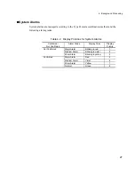
Page 41: ...following alarm grades Table 4 2 Display Priorities for System Alarms Confirmed Not Confirmed Alarm Grade Display Color Display Priority Not Confirmed Major Alarm Blinking in red 1 Medium Alarm Blinking in violet 2 Minor Alarm Blinking in yellow 3 Confirmed Major Alarm Red 5 Medium Alarm Violet 6 Minor Alarm Yellow 7 Normal Green 9 ...

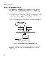
Page 42: ... on the event conditions of the status signal If they are met SVR DS sends an event condition change message to OIS DS It also performs guidance voice output and history message printing For a redundant system SVR DS event occurrence and recovery are mirrored to both stations Ethernet DS SVR Event Condition DS SVR Event Condition DS HI Guidance Voice Output History Message Printing Mirroring Event...

Page 43: ...functions for message printing 1 Alternative Printer Function You can switch to an alternative printer when the specified printer fails 2 Filtering Function You can restrict message printing by specifying message printing prohibiting event conditions for related events when tag event conditions of process and system alarms and guidance are met For message printing the following items are registere...

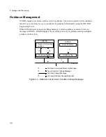
Page 44: ...an event change message it sends a guidance occurrence recovery message to OIS DS OIS DS displays the occurrence recovery of guidance and representative guidance on the screen OIS DS Ethernet Guidance Cache Process that requires guidance ƒ SVR DS Guidance Tag Event Condition Event Condition Change Message ƒ Guidance Change Message Guidance Retrieval Request Response Guidance Occurrence Recovery Me...

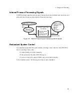
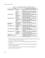
Page 45: ...ate Alarm Detection Monitor Function Standard Screen Historical Graphic Report Application Data Retrieval Input Output Alarm Notification Figure 4 6 Internal Process Signal Processing and I O Signals Redundant System Control In a redundant system SVR DS online standby switching is done when the online SVR DS is down Switching is done when 1 online standby is switched manually 2 the operation of th...

Page 46: ...d only by Online SVR s History Message Save Data Save Performed at down recovery of Online SVR s Mirroring Performed at down recovery of Online SVR s Read Read from Online SVR s History Message Printing Printing Occuured only by Online SVR s Diagnosis Diagnosis of each shared printer is individually performed External Alarm Output ADIO Output Performed by both Online and Standby SVR s PCS Output O...

Page 47: ...4 Background Processing 33 In the SVR Station State Display check that the process execution state during historical mirroring and report data mirroring goes Suspended ...

Page 48: ...4 Background Processing 34 ...

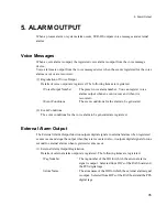
Page 49: ...ns The event conditions for the alarm to be generated 2 Event Conditions The event conditions for the voice alarm to be generated are registered External Alarm Output The External Alarm Output function outputs digital signals to external alarms when registered events occur and stops the output when they are recovered Also it outputs digital signals for one second to external alarms when registered...

Page 50: ...rm output to be generated ŸOutput Type Selected from the type which outputs from the event occurrence to recovery and the type which outputs only for one second when the event occurs 2 Event Conditions The event conditions for the external alarm output generation are registered ...

Page 51: ... the allowable time difference within five seconds is exceeded clocks are synchronized to the system clock of own SVR DS If multiple SVR DS s are connected to the TOSDIC CIE DS system one of them is used for this purpose Ethernet Control LAN Time Monitoring System Clock 10 10 00 SVR s Clock 10 10 00 OIS s Clock 10 09 58 PCS s Clock 10 09 57 OIS s Clock 10 10 01 OIS s Clock 10 09 59 Figure 6 1 Time...

Page 52: ...6 Time Monitoring 38 ...

Page 53: ...ag data from PCS in an application process and perform operations of the data You can write the result to a parameter tag and display it on the graphic screen SVR DS OIS DS PCS Data Read of PCS Tag Alarm Occurrence Event Condition Scheduler Event Notification API Process Operation Internal Tag Parameter Tag Data Write Startup Graphic Screen Event Setting Data Read Figure 7 1 An Example of a User A...

Page 54: ...en event conditions are met l l l lData Sharing When data is shared among multiple applications you can use the Network Database to mirror written data to all SVR DS s l l l lRAS Functions Since user application programs are managed by SVR DS s scheduler they a detect abnormal termination of a process or WDT Watchdog Timer When an error occurs system alarm notification and RAS information save can...

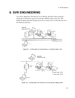
Page 55: ...gineering Tools SVR DS OIS DS and the OIS SVR Engineering Tools are connected via a Control System LAN or Information System LAN OIS SVR Engineering Tool Control System LAN A Control System LAN B Figure 8 1 An Example of Connection to a Control System LAN OIS SVR Engineering Tool Control System LAN A Control System LAN B Figure 8 2 An Example of Connection to a Information System LAN ...

Page 56: ...8 SVR Engineering 42 ...

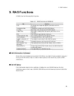
Page 57: ... validity check function for the UNIX file system Memory Patrol Patrolling all memory and correction of 1 bit errors Hard Operation Time Monitoring Total operation time of all units fan battery etc in SVR DS Network Monitor Access diagnosis functions for other nodes or peripheral devices on the same network Application Monitor The application error detection function l l l lRAS Information Collect...

Page 58: ...uch as FTP can be performed for the RAS information of OIS DS SVR DS by connecting a remote computer to the OIS DS SVR DS network via a telephone line OIS DS OIS DS SVR DS Telephone Line File Transfer via FTP RAS Information Collection Computer Figure 9 1 Remote Diagnosis ...

Page 59: ...unction is handled by software Input Device Mouse and touch panel optional Dedicated operator controller optional Engineer controller optional Touch panel and mouse are used simultaneously Redundancy Stand alone distribution SVR DS Dual wait redundancy optional OIS DS Parallel redundancy Peripheral device sharing System information is distributed mirrored Security User management by NT s logon Ala...

Page 60: ...ice Signal Category 64 signal categories system Tagging Directly registered to tags Service Name Tag Number Character Tag Name Signal Category Name Indicator Name Station Name Industrial Unit Tagging Character Guidance Name Trend Group Name ANK 16 characters ANK 32 characters ANK 16 characters ANK 16 characters ANK 32 characters ANK 16 characters ANK 16 characters ANK 40 characters ANK 30 characte...

Page 61: ...e message with signal category 40 bytes detailed message 512 bytes A event condition is used as an output trigger Voice Output 1024 messages system A event condition is used as an output trigger Buzzer Output 7 types 2 output types With Stop Broadcasting Function via Auto Stop BR External Alarm Output 64 items Tagging PCS output is possible 2 points of the RAS board DO output Clock All nodes are u...

Page 62: ...Appendix1 System Specification Of OIS DS SVR DS 48 ...

Page 63: ......

Page 64: ...TOSHIBA TOSHIBA CORPRATION 1 1 SHIBAURA 1 CHOME MINATO KU TOKYO 105 8001 JAPAN PHONE 3457 4900 ...

Reviews: