


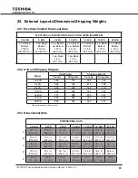
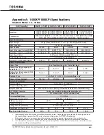

50
1600XP/XPi Series Installation and Operation Manual – 60616-012
22. Optional Receptacle Panel Installation Instructions
These are the instructions for installing the optional Modular Output
Receptacle Panels for the 1600XP/
1600XPi Series UPS. These instructions apply to all UH3-RP-XXX panel options.
WARNING: The work outlined in these instructions is to be performed only on a completely de-energized
UPS system.
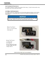
Refer to Figure 1 for location of UPS referenced material. Refer to Figure 2 for material referring to the
receptacle panel module. There are different panels available depending on the UPS typeform.
Step 1: Remove the modular receptacle panel cover plate.
On the rear of the UPS, locate the cover plate for the receptacle panel module interface
(See Figure 1).
Remove the 6 mounting screws.
Remove the cover plate. A square-shaped plug will be exposed.
Step 2: Snap-In Output Receptacle modular panel.
Carefully mate the square-shaped connector on the UPS to its matching counter part on the rear
of the modular panel.
Step 3: Mount the receptacle panel.
Attach the screws removed from the cover plate through the mounting holes of the receptacle
panels and back into the UPS mounting points.
Mounting
Mounting
Screws
Receptacle
Panel
Connector
Figure 1
Figure 2
Summary of Contents for 1600XP SERIES
Page 2: ...b 1600XP XPi Series Installation and Operation Manual 60616 012 ...
Page 6: ...f 1600XP XPi Series Installation and Operation Manual 60616 012 ...
Page 10: ...iv 1600XP XPi Series Installation and Operation Manual 60616 012 ...
Page 74: ...64 1600XP XPi Series Installation and Operation Manual 60616 012 ...
Page 112: ...B 32 1600XP XPi Series Installation and Operation Manual 60616 012 ...
Page 115: ...C3 1600XP XPi Series Installation and Operation Manual 60616 012 8 10 kVA Dimensions ...
Page 132: ...E2 1600XP XPi Series Installation and Operation Manual 60616 012 ...
Page 139: ......


