background image

24

1600ep Series instruction manual

Online Mode

Online Mode (Run operation) 


The  following  illustration  shows  circuit  power  flow  when  the  UPS  is  operating  normally  in  the 

online 

mode. The UPS rectifier, including a boost chopper circuit, converts AC input power to DC power. The 

boost chopper circuit maintains a constant voltage, with current limiting, for charging the batteries. it also 

supplies a DC voltage of the proper level to the inverter section. the inverter section generates a high 

quality sine wave output voltage. the unit’s batteries are always maintained in a constantly charged state 

when the UpS is in the run operation mode.


Static-Bypass Mode (Stop operation)

If the UPS unit is severely overloaded or develops an internal fault, power flow is automatically switched 

from the unit’s main circuit to the bypass circuit. Power flow through the bypass is shown in the following 

illustration. this change-over occurs automatically in phase in less than 4 milliseconds. the switching 

period is not long enough to cause interruptions to occur in most loads. 

If the power flow is transferred to the bypass circuit because of an overload and that overload condition 

ends within a specified period of time then the power flow will be transferred back to the 

Online mode 

(run operation)

 automatically.  

If the power flow is transferred to the bypass circuit due to an external 

fault the UpS will shut down 

power through the bypass to the load and indicate a system fault message.  

If the power flow is transferred to the bypass circuit due to an internal fault the UPS will continue to 

supply power to the load through the bypass and indicate a system fault message (see system fault 

message DC-oC on 

page

 43). 

If the power flow is transferred to the bypass circuit due to an overload condition (see system warning 

message 

OL: redUCe LOAd

 on 

page 39 

and 

AUTO RETRANSFER

 on 

page 

41), then the power 

flow will automatically transfer from the UPS’s bypass circuit back to the inverter circuit after removing 

the overload if set to do so (see auto-transfer setting on 

page

 35).


POWER FLOW IN ONLINE MODE FOR ALL MODELS

POWER FLOW IN BYPASS MODE FOR ALL MODELS

Summary of Contents for 1600EP Series

Page 1: ...ble Power System UPS single phase 3 6 RoHS 3 6 6 8 10 14 18 22 March 2008 Part 55288 002 Manufactured in the USA Copyright 2008 TOSHIBA International Corporation All rights reserved 1600EP SERIES instruction MANUAL ...

Page 2: ......

Page 3: ...ations in equipment or to provide for every possible contingency concerning installation operation or maintenance Should further information be required or if problems arise which are not covered sufficiently contact your Toshiba sales office The contents of this instruction manual shall not become a part of or modify any prior or existing agreement commitment or relationship The sales contract co...

Page 4: ...anty period for the UPS or UPS part is 36 months from the shipment date see Toshiba International Corporation bill of lading Unless otherwise specified the warranty period for a UPS battery is 24 months from the shipment date see Toshiba International Corporation bill of lading JOB NUMBER MODEL NUMBER SERIAL NUMBER APPLICATION SHIPMENT DATE INSTALLATION DATE INSPECTED BY ...

Page 5: ...eferences appearing in this manual are registered trademarks of their respective owners Toshiba International Corporation shall not be liable for direct indirect special or consequential damages resulting from the use of the information contained within this manual This manual is copyrighted No part of this manual may be photocopied or reproduced in any form without the prior written consent of To...

Page 6: ...1600EP Series Instruction Manual This page intentionally left blank ...

Page 7: ...ions 7 Conductor Routing and Grounding 7 Operating Precautions 8 Equipment Warning Labels 9 UPS Connections 11 Communication Interfaces 12 UPS Stop Signal Operation 13 RS 232C 14 RemotEye II Network Card 14 UPS Specifications 15 Operating the UPS 21 Battery Backup Time and Discharge Process 21 Starting the UPS 22 Battery Recharging 23 Online Mode 24 Online Mode Run operation 24 Static Bypass Mode ...

Page 8: ...ssages 39 System Fault Messages 40 Status Change Indications 41 UPS Protection System 42 System Protection Features 42 System Protection Functions 42 Preventive Maintenance Parts Replacement 44 Preventive Maintenance 44 Parts Replacement 44 Optional Receptacle Panel Installation Instructions 45 Optional MB Maintenance Bypass Units 46 External Layouts Dimensions Shipping Weights 48 Dimensional Data...

Page 9: ...mbols are used in this manual they will include important safety information that must be carefully followed Safety Alert Symbol indicates that a potential personal injury hazard exists Prohibited Symbol indicates DO NOT take action Mandatory Symbol indicates that the following instruction is required Ground Symbol indicates the location of the equipment grounding conductor Electrical Voltage Shoc...

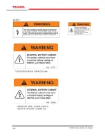
Page 10: ...by the safety alert symbol indicates that a potentially hazardous situation exists if not avoided may result in loss of life or serious injury to personnel caution The word CAUTION in capital letters preceded by the safety alert symbol indicates that a potentially hazardous situation exists if not avoided may result in minor or moderate injury caution The word CAUTION in capital letters without th...

Page 11: ...are not equipped with an over current protection device nor do they have an output disconnect for the AC output Therefore a user installed circuit breaker should be provided between the UPS output and the load input The maximum ambient operating temperature is 104 F 40 C Battery servicing should be performed by qualified Toshiba representative only Unauthorized personnel should not service batteri...

Page 12: ...watches rings or other metal objects Use tools with insulated handles to prevent inadvertent shorts Wear rubber gloves and boots DO NOT place tools or any metal parts on top of batteries Determine if the battery is inadvertently grounded If inadvertently grounded remove source of ground Warning Contact with any part of a grounded battery can result in electrical shock The likelihood of shock will ...

Page 13: ...ent unit The UPS unit assures safe and reliable operation of critical office equipment This can range from word processors and personal computers to mini computers and local area networks All units feature an audible alarm which sounds if the battery voltage drops below a specified minimum during use This is an additional aid to help in retaining the valuable office data banks All units allow for ...

Page 14: ... store the UPS in the original shipping container and place on a wood or metal pallet Storage temperature 4 104 F 20 40 C The optimum storage temperature is 70 F 21 C A higher ambient temperature will require recharging more frequently during storage Avoid storage locations that Are subject to extreme temperature changes or high humidity Are subject to high levels of dust or metal particles Are su...

Page 15: ...ce some sensitive devices that are operating near by If such interference is experienced the UPS should be installed farther away from the affected equipment and or powered from a different source than that of the affected equipment The user should provide output over current protection for hardwired UPS systems See the section titled Specifications on page 15 and 18 for the device rating After en...

Page 16: ...E LED has gone out before opening the door of the UPS once the UPS power has been turned off DO NOT attempt to disassemble modify or repair the UPS Call your Toshiba sales representative for repair information Turn the power on only after installing ALL of the covers DO NOT remove any covers of the UPS when the power is on If the UPS should emit smoke produce an unusual odor or make sound turn the...

Page 17: ...ersonnel NO USER SERVICEABLE PARTS INSIDE To reduce the risk of fire or electric shock install in a temperature and humidity controlled indoor area free of conductive contaminants En cas utilisation en atmosphere controlee Consulter la notice technique Note Service personnel only Hazardous live parts inside the UPS are energized from the battery supply even when the input AC power is disconnected ...

Page 18: ...10 1600EP Series Instruction Manual ...

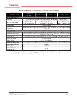
Page 19: ...nd Tightening Torque Use the following table to select the recommended wire size and terminal lug tightening torque for I O wire connections Item Terminal Number AWG 3 6RoHS kVA AWG 3 6 kVA AWG 6 kVA AWG 8 kVA AWG 10 kVA AWG 14 18 kVA AWG 22 kVA Tightening Torque lb in N m AC Input Lines 1 and 2 12 8 12 8 10 8 8 1 0 6 1 0 4 1 0 1 1 0 14 2 1 56 AC Output Lines 4 5 and 7 12 8 12 8 10 8 8 1 0 6 1 0 4...

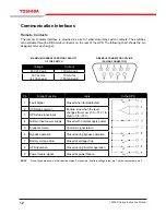
Page 20: ... rms 42 Vac peak 70 mA rms 100 mA peak Pin Signal Function Logic In the UPS 1 Fault Signal Closed when fault detected 2 UPS stop common Backup stop when the level changes from Low 3 to 15 V to High 3 to 15 V 3 UPS stop signal input 4 Normal input power supply Closed with normal supply power 5 Signal common Common signal return 6 Bypass operation Closed during bypass operation 7 Battery voltage dro...

Page 21: ...down process the OS sends a stop signal to the UPS and the UPS stops When the power recovers the UPS automatically restarts the OS within 10 minutes after the recovery from power failure If the line power recovers while the OS is in the shutdown process the OS continues the shutdown process and signals the UPS to stop The UPS temporarily cuts off the output 10 20 seconds and then restarts the OS I...

Page 22: ...nput CTS Clear to send 9 This pin is not used RemotEye II Network Card The RemotEye II is an optional network card for the Toshiba UPS This card slides into a slot located on the back side pages 47 48 of the UPS The card provides a network or LAN based communication interface for the UPS When installed the UPS can be managed remotely using the common SNMP and HTTP web based network protocols The f...

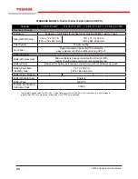
Page 23: ...dc 216 Vdc 288 Vdc Output Characteristics Output Voltage Single phase 240 208 120 V Output Voltage Regulation 3 Output Frequency 0 5 Hz 1 Hz 1 5 Hz factory or authorized service center selectable only AUTO MAN Frequency Factory or authorized service center selectable only Voltage THD 3 for linear load 6 for non linear load Common Mode Noise 0 5 Vrms Rated Load Power Factor 0 85 0 6 1 0 lagging Eff...

Page 24: ...2 Backup 16 Faults Applications Switches Generator compatibility Bypass Switch Bypass Disable Static switch cycle 50 Hz 5 ms 60 Hz 4 16 ms Automatic Retransfer Factory or authorized service center selectable only User Interface Provided Can be disabled from front panel Real Time Clock Schedule Operation Standard Minimum 3 days memory backup during power loss RUN STOP Disable Schedule ON OFF operat...

Page 25: ...low for easy replacement of fans without turning UPS off Battery System Battery Replacement Slide out battery packs accessible from front of UPS Factory or authorized service center serviceable only Battery Packs Designed for battery acid leakage containment with six 6 batteries per pack Battery Pack Size HxWxD max 5 x 7 3 x 18 2 in 127 x 185 x 462 mm Battery Pack Quantity 2 3 4 Battery Manufactur...

Page 26: ...acteristics Output Voltage Single phase 240 208 120 volts Output Voltage Regulation 3 Output Frequency 0 5Hz 1Hz 1 5Hz factory or authorized service center selectable only AUTO MAN Frequency Factory or authorized service center selectable only Voltage THD 3 for linear load 6 for non linear load Common Mode Noise 5 Vrms Rated Load Power Factor 0 85 0 6 1 0 lagging Efficiency AC DC AC 83 without bat...

Page 27: ...s Applications Switches Generator compatible Bypass Switch Bypass Disable Static switch 1 4 cycle 50Hz 5 ms 60Hz 4 16 ms Automatic Retransfer Factory or authorized service center selectable only User Interface Provided Can be disabled from front panel Real Time Clock Schedule Operation Standard Minimum 3 days memory backup during power loss RUN STOP Disable Schedule ON OFF operation of UPS using c...

Page 28: ...lacement of fans without turning UPS off Battery System Battery Replacement Slide out battery packs accessible from front of UPS factory or authorized service center serviceable only Battery Packs Designed for battery acid leakage containment with 6 batteries per pack Battery Pack Size HxWxD max 5 x 7 3 x 18 2 in 127 x 185 x 462 mm Battery Pack Quantity 4 8 Battery Manufacturer Enersys Battery Typ...

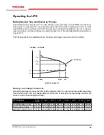
Page 29: ...hically shows the battery discharge process at full load conditions Battery Low Voltage Tolerances Excessive discharge will cause the UPS battery voltage to drop The chart shown below lists the voltage level at which each UPS low voltage alarm will sound and at what level the low voltage condition will cause the unit to automatically shut down UPS Capacity 3 6 kVA RoHS 3 6 kVA 6 kVA 8 kVA 10 kVA 1...

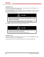
Page 30: ...r at least 24 hours input breaker on before operating the connecting load Using the UPS without charging the battery shortens the battery backup operation time which may result in the destruction of data in case of a power failure Press RUN key to begin UPS operation see page 29 for startup screens Caution If the input breaker is turned off while UPS is in the bypass state the output power stops A...

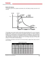
Page 31: ...ully charged state In the third period a slight trickle current continues to flow into the batteries to keep them fully charged and floating at the normal Vdc level A full recharge usually requires 24 hours 90 recharge in 12 hours after a complete discharge The following chart shows the rated maximum and minimum battery voltages and the charge current for each of the sizes Rated Battery Voltages M...

Page 32: ...ds The switching period is not long enough to cause interruptions to occur in most loads If the power flow is transferred to the bypass circuit because of an overload and that overload condition ends within a specified period of time then the power flow will be transferred back to the Online mode run operation automatically If the power flow is transferred to the bypass circuit due to an external ...

Page 33: ...Power Off Function These units are equipped with terminals for receiving an emergency power off EPO command via a closed contact switch at a remote location see Terminal Block Details on page 11 and terminal block location on page 37 38 This safety feature enables quick shut down of the UPS s AC output and battery circuits Usually the emergency power off switch is installed in a central location t...

Page 34: ...an overload condition The following chart shows the audible alarm pattern durations for each condition Time units are shown in seconds The audible alarm can be silenced by pressing key on the front panel see page 27 Audible Alarms Condition Audible Pattern UPS in battery Backup mode UPS low Battery voltage Overload Fault Run Shift Select 0 5 s 9 s 1 s 1 s 1 s 1 s 1 s 0 5 s ...

Page 35: ... operation of the UPS It should be used in conjunction with the LED display see page 28 39 40 and the audible alarms see page 26 for total system monitoring The LCD screen displays information which may be shown only on specific lines of the display This information is determined by the UPS operating mode and conditions These messages are shown in the LED displays and LCD screens on pages 28 throu...

Page 36: ...ft key silences the trouble indicator audio alarm Stops the UPS and switches to bypass mode Light Emitting Diodes LED The following table describes the various LED behaviors and the system indications they provide LED Behavior Significance Meaning Lights in green Run Normal UPS inverter in operation Flashes in green UPS output off Lights in red UPS failure no output LED OFF Stop Bypass operation o...

Page 37: ...equencing System Overview screens These screens notify operator of steps taken by UPS during its initialization The sequence of Start Up screens begins when AC input power is detected at UPS input If the correct AC input power is available and no abnormal operating conditions are present then the following system message will be displayed on the LCD screen Next the LCD will report the current date...

Page 38: ... begin a battery test if the setting is enabled see page 35 This test ensures a healthy battery system is available should it be necessary to support the load During the test the LCD reports the current battery voltage as a percent of its expected value at full charge This figure will drop throughout the test as the battery voltage is intentionally lowered to test performance The test lasts for ab...

Page 39: ...ted nominal DC voltage of the batteries Displays the date and time setting If the SHIFT SELECT key is pressed from any one of the Timer Start Data Timer Stop Data Weekly Schedule Special Operate and Special Off time screens then special Data Display screens are viewed These functions can only to be changed via the serial communication interface see page 32 1 2 3 4 5 6 INPUT VOLTAGE V INPUT FREQUEN...

Page 40: ...Data screen page 31 Continued from Timer Stop Data screen page 31 Continued from Weekly Schedule Data screen page 31 Continued from Special Operate Data screen page 31 Continued from Special Off Time Data screen page 31 Notes To access the data setting screens pess the SET MONITOR key from any of the see page 33 Data Settings screens Pressing the SHIFT SELECT and CANCEL key returns to the Data Dis...

Page 41: ...ANGE SELECT LCD SLEEP 3 MIN TO CHANGE SELECT AUTO RUN NO TO CHANGE SELECT AUTO RETRAN YES TO CHANGE SELECT REMOTE BYPASS TO CHANGE SELECT PERFORM BAT TEST PUSH SELECT VOLTAGE ADJ 0 TO CHANGE SELECT COMM MODE RS232 TO CHANGE SELECT BAUD RATE 1200 TO CHANGE SELECT INI BAT TST YES TO CHANGE SELECT AUTO BATT TST NO TO CHANGE SELECT BATTERY TEST DATA SET SELECT KEYS LOCK DIS TO CHANGE SELECT DEFAULT SE...

Page 42: ...r LCD SLEEP 30 MIN TO ACCEPT SET Loops through both possibilities Returns to Data Setting screens with new value applied Cont d from LCD Display Time data setting screen page 33 AUTO RUN YES TO CHANGE SELECT Shift Select Set Monitor AUTO RUN YES TO ACCEPT SET AUTO RUN NO TO CHANGE SELECT Shift Select Set Monitor AUTO RUN NO TO ACCEPT SET Loops through both possibilities Returns to Data Setting scr...

Page 43: ...32 TO CHANGE SELECT Shift Select Set Monitor COMM MODE RS232 TO ACCEPT SET COMM MODE SNMP TO CHANGE SELECT Shift Select Set Monitor COMM MODE SNMP TO ACCEPT SET Loops through both possibilities Returns to Data Setting screens with new value applied Cont d from Comm Mode data setting screen page 33 Set to YES the unit will automati cally retransfer back to UPS mode after transferring momentarily to...

Page 44: ...all months of the year Cont d from Date and Day data setting screen page 33 Shift Select Set Monitor 11 28 2007 MON FOR NEXT SELECT 12 28 2007 MON TO CHANGE SELECT Returns to Day and Date Data Setting screen with new value applied Shift Select Set Monitor TIME 10 38 58 FOR NEXT SELECT Shift Select Set Monitor TIME 12 38 58 FOR NEXT SELECT Shift Select Set Monitor TIME 11 38 58 FOR NEXT SELECT Loop...

Page 45: ...hift Select Set Monitor INTERVAL 99 DAY TO ACCEPT SET Loops through 99 possibilities Returns to Data Setting screens with new value applied Cont d from Batt Test Interval data setting screen page 33 INTERVAL 2 DAY TO CHANGE SELECT Shift Select Set Monitor INTERVAL 2 DAY TO ACCEPT SET The Battery Test Interval variable se lects the interval in days that the bat tery test will be conducted The op ti...

Page 46: ...tests to insure that the batteries remain in a fully charged state This parameter allows the user to off set the output voltage while the unit is running on lline in 1 increments over a range of 5 total offset Default value is 0 This parameter has no options to set Pressing the SHIFT SET button while this message is displayed will cancel timer settings BATTERY TEST Shift Select Set Monitor TO BEGI...

Page 47: ...y shut down the load equipment in an orderly fashion and then press the stop key Amber LED Flashes Meaning The unit is overheated warning is given when the internal temperature reaches and exceeds 50 C rise 40 C ambient Action Check to see if the ambient temperature is abnormally high 40 C or more If so turn on air conditioning and check the ventilation fan at the back of the unit for operation or...

Page 48: ...urred Action UPS is probably faulty Check the UPS operating conditions at time of fault Not advisable to try restarting Call for service Red LED Flashes Meaning DC overvoltage condition occurred Action UPS is possible faulty input wiring error input overvoltage or connection of a motor load Try restarting If condition persists call for service Red LED Flashes Meaning Output overload condition occu...

Page 49: ... the output frequency Meaning The battery level has dropped low about 90 or less during operation Continued operation in this mode will deplete battery and cause output shut down Action Immediately shutdown the load equipment in an orderly fashion and then press the STOP key Meaning A start notice is displayed 5 minutes before starting the UPS when the start timer is set by communication and conti...

Page 50: ...or Control malfunction Fuse opened Load issue Overload Short circuit at load Operation Mode After Fault Bypass operation Chopper and inverter are stopped Inverter OL Transfer to bypass Bypass OL Inverter chopper stopped Audible Alarm Yes Continuous buzzer See Audible Alarm Functions on page 26 Visible Alarm Red Fault LED on Inverter OL Fault lamp off Bypass OL Fault lamp on Relay Contact Alarm Fau...

Page 51: ...VERHEAT DC OV DC OC Cause Fan failure High ambient temperature Chopper malfunction Inverter chopper fault Operation Mode After Fault Shutdown No output Bypass operation Chopper and inverter are stopped Inverter OL Transfer to bypass Audible Alarm Yes Continuous buzzer Visible Alarm Red Fault LED on Relay Contact Alarm Fault relay closed Bypass relay closed Auto retransfer No ...

Page 52: ...intenance details which are described directly above this caution Parts Replacement The following list shows recommended intervals for periodic replacement of certain UPS parts Aluminum electrolytic capacitors Replace once every 5 years Fuses Replace once every 7 years Cooling fan When operated in an ambient temperature of 86 F 30 C to 104 F 40 C replace every 3 5 years When operated in an ambient...

Page 53: ...acle panel module Step 1 Remove the modular receptacle panel cover plate On the rear of the UPS locate the cover plate for the receptacle panel module interface see Figure 1 Remove the 6 mounting screws Remove the cover plate A square shaped plug will appear exposed near the upper left corner of the uncovered slot Step 2 Snap In Output Receptacle modular panel Carefully mate the square shaped conn...

Page 54: ...nstructions below when switching to and from the Maintenance Bypass mode From Inverter Mode to Maintenance Bypass Mode Turn the RUN STOP switch to the STOP position on the UPS Turn the Maintenance Bypass Switch to the Bypass position The Bypass LED should be ON and the UPS LED should be OFF The LEDs are next to the Maintenance Bypass switch on the back of the UPS Turn the MCCB input breaker on the...

Page 55: ...ions must be made to the Utility Panel and the Load Panel The Main UPS output is located on the terminal block on the back of the UPS TB 4 X1 and TB 7 X3 240 VAC Main output Utility Panel L1 L2 n G lOAD Panel L1 L2 n G UPS L1 L2 G x1 x3 n G Maintenance Bypass ...

Page 56: ...5 6 in 904 mm 35 6 in 904 mm 35 6 in 904 mm E 2 8 in 72 mm 2 8 in 72 mm 2 8 in 72 mm 2 7 in 69 mm 2 7 in 69 mm 3 47 in 88 mm 3 47 in 88 mm 3 47 in 88 mm Electrical Conduit Knock out Data electrical conduit knock out hole sizes diameter 3 6 kVA RoHS 3 6 kVA 6 kVA 8 kVA 10 kVA 14 kVA 18 kVA 22 kVA 6 ea 1 125 in 28 575 mm 6 ea 1 125 in 28 575 mm 6 ea 1 125 in 28 575 mm 5 ea 1 72 in 43 69 mm 5 ea 1 72...

Page 57: ...49 1600EP Series Instruction Manual External Layout for 3 6 kVA RoHS 3 6 kVA and 6 kVA units ...

Page 58: ...out for 8 kVA 10 kVA 14 kVA 18 kVA and 22 kVA units Front View back View 14 18 kVa Side View back View 10 kVa Air air Flow Display panel terminal block Cover mCCb Cooling Fans Snmp port Snmp port remote Contacts remote Contacts 14 18 22 kVA 8 10 kVA ...

Page 59: ...19 mode 22 24 28 29 overload capacity 18 switch 19 C capacitors 44 Common mode noise 5 18 Communication interface 12 Conduit Knock out sizes 48 Cooling fan 44 D Data See Data Display Screens Data Setting Screens Data Display Screens 28 29 32 Data Setting Screens 28 31 33 38 DB9 Connector female pinouts 14 male pinouts 12 Dimensional Data 48 Disposal 6 E Emergency Power Off EPO function 8 11 25 29 ...

Page 60: ...Emitting Diode displays 27 Lifetime battery 19 44 battery warning light 39 capacitors Aluminum electrolytic 44 fan cooling 44 fuses 44 Liquid Crystal Display LCD Functions 27 Low Voltage Tolerance 21 M Maintenance Bypass switching to and from 46 Maintenance Bypass voltage restrictions 46 Maintenance Bypass Unit 46 maximum ambient operating temperature 3 Mode AC Input 24 Battery Backup 25 display 2...

Page 61: ... 21 Signal Function RS 232C 12 Signal Words 2 Size battery packs 20 UPS dimensions 20 wire 11 Specifications 15 Start Up Screens 29 Starting the UPS 22 Status Change Indications 41 Stopping the UPS 22 41 Stop Signal Operation 13 Storage 6 19 temperature 19 synchronization frequency tolerance 41 System Fault Messages 40 System Warning Messages 39 T Terminal Block 11 Theory of operaton 5 torque tigh...

Page 62: ...54 1600EP Series Instruction Manual ...

Page 63: ......

Page 64: ...INDUSTRIAL DIVISION 13131 West Little York Road Houston Texas 77041 Tel 713 466 0277 Fax 713 466 8773 US 800 231 1412 Canada 800 872 2192 Mexico 01 800 527 1204 www Toshiba com ind Printed in the U S A ...

Reviews: