


6. Subtract the front dimension from the rear
dimension to calculate the blade pitch.
7. Adjust the jam nuts securing the rear deck
yokes/chains to raise the rear of the deck so
that the blade pitch is set to 5/16 inch (8 mm)
(Figure 77).
Figure 77
1. Chain
3. Jam nut
2. Yoke
4. Mower deck
Replacing the Grass
Deector
An uncovered discharge opening could
allow the lawn mower to throw objects in
the operator’s or bystander’s direction and
result in serious injury. Also, contact with
the blade could occur.
•
Never operate the lawn mower without a
mulch kit or grass deflector installed.
•
Make sure the grass deflector is in the
down position.
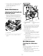
1. Lower the cutting unit to the shop floor, move
the throttle lever to the Slow position, stop the
engine, set the parking brake, and remove the
ignition key.
2. Remove the locknut, bolt, spring and spacer
holding the deflector to the pivot brackets
(Figure 78). Remove damaged or worn grass
deflector.
Figure 78
1. Bolt
5. Spring installed
2. Spacer
6. Grass Deector
3. Locknut
7. Left hand hook end of
spring, place behind deck
edge before installing bolt
4. Spring
8. Right hand hook end of
spring
3. Place the spacer and spring between
the replacement grass deflector brackets
(Figure 78). Place the left hand J hook end of
the spring behind the deck edge.
Note:
Make sure the left hand J hook end
of the spring is installed behind the deck edge
before installing the bolt as shown in Figure 78.
4. Install the bolt and nut. Place the right hand
J hook end of the spring around the grass
deflector (Figure 78).
Important:
The grass deflector must be
able to lower down into position. Lift the
deflector up to test that it lowers into the
full down position.
Cleaning
Cleaning Under the Mower
Remove the grass buildup under the mower daily.
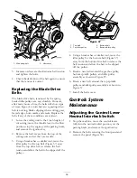
1. Disengage the PTO, move the motion control
levers to the neutral locked position and set
the parking brake.
2. Move the throttle lever to the Slow position,
stop the engine, remove the key, and wait for
all moving parts to stop before leaving the
operating position.
67
Summary of Contents for Groundsmaster 7200 Series
Page 9: ...Slope Chart 9 ...
Page 44: ...Figure 39 44 ...
Page 70: ...Schematics Electrical Schematic Rev A 70 ...
Page 71: ...Hydraulic Schematic Rev A 71 ...


