


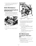


Figure 58
1. Front panel bolts
3. Loosen the 2 screws securing the interlock
switch (Figure 59).
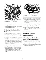
Figure 59
1. Control lever
3. Screws
2. Neutral interlock switch
4. 0.015 to 0.045 inch (0.4 to
1 mm)
4. Holding the control lever against the frame,
move the switch toward the lever until the
distance between lever and switch body is
0.015 to 0.045 inch (0.4 to 1 mm) (Figure 59).
5. Secure the switch.
6. Repeat steps 3 to 5 for the other lever.
7. Install the front panel.
Adjusting the Control Lever
Neutral Return
If the motion control levers do not align with the
neutral slots when released from the reverse drive
position, adjustment is required. Adjust each lever,
spring, and rod separately.
1. Disengage the PTO, move the motion control
levers to the neutral locked position and set
the parking brake.
2. Move the throttle lever to the Slow position,
stop the engine, remove the key, and wait for
all moving parts to stop before leaving the
operating position.
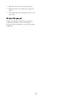
3. Remove the bolts securing the front panel and
remove the panel (Figure 60).
Figure 60
1. Front panel bolts
4. Move one of the levers to the neutral position
but
not locked
(Figure 62).
5. Pull the lever back until the clevis pin (on an
arm above the pivot shaft) contacts the end
of the slot (just beginning to put pressure on
the spring) (Figure 61).
57
Summary of Contents for Groundsmaster 7200 Series
Page 9: ...Slope Chart 9 ...
Page 44: ...Figure 39 44 ...
Page 70: ...Schematics Electrical Schematic Rev A 70 ...
Page 71: ...Hydraulic Schematic Rev A 71 ...


