


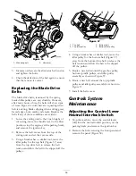


Figure 65
1. Stop bolt
3. Jam nut
2. Control lever
4. 0.060 inch (1.5 mm)
5. Thread the stop bolt all the way in (away from
the control lever).
6. Push the control lever all the way forward until
it stops and hold it there.
7. Thread the stop bolt out (towards the control
lever) until there is a gap of 0.060 inch (1.5
mm) between the head of the stop bolt and
the control lever.
8. Tighten the jam nut to secure the stop bolt in
place.
9. Repeat steps 4 through 8 for the other control
lever.
10. Install the front panel.
Note:
If you wish to reduce the maximum
machine speed, set the speed for both control
levers as directed above, then back each stop bolt
out an equal amount toward the control lever until
you reach the maximum speed you desire (you will
likely have to test your adjustment several times).
Ensure that the machine drives straight and does
not turn when both control levers are pushed all
the way forward. If the machine turns, you do
not have the stop bolts evenly set and will need
to adjust them further.
Adjusting the Tracking
1. Disengage the PTO, move the motion control
levers to the neutral locked position and set
the parking brake.
2. Move the throttle lever to the Slow position,
stop the engine, remove the key, and wait for
all moving parts to stop before leaving the
operating position.
3. Loosen the bolts securing the control levers
(Figure 66)
Figure 66
1. Control lever
3. Bolts
2. Control lever post
4. Have someone push the control lever posts
(not the control levers) all the way forward into
the maximum speed position and hold them
there.
5. Adjust the control levers so that they line up
(Figure 67) and tighten the bolts, securing the
levers to the posts.
60
Summary of Contents for Groundsmaster 7200 Series
Page 9: ...Slope Chart 9 ...
Page 44: ...Figure 39 44 ...
Page 70: ...Schematics Electrical Schematic Rev A 70 ...
Page 71: ...Hydraulic Schematic Rev A 71 ...


