Verdin Carrier Board Design Guide
Preliminary
– Subject to Change
Toradex AG l Ebenaustrasse 10 l 6048 Horw l Switzerland l +41 41 500 48 00 l
l
Page | 13
*May differ on some modules. Please check the datasheet of the respective module or the Pinout
Designer tool.
2.1.3
"Module-specific" Interfaces
"Module-specific" interfaces allow for the possibility of including and providing module interfaces to
customers which may not be widely adopted (yet), or may be specific to a device or groups of
devices. They also offer a mechanism for extending features which are present on "Always
Compatible" or "Reserved" interfaces, e.g. providing additional PCI-Express lanes.
It should be noted that "Module-specific" interfaces will be kept common across modules that share
such interfaces (whenever possible). For example, if both module A and module B have an LVDS
interface in the "Module-specific" category, then they shall be provided on the same "Module-
specific" pins. Hence, both module A and module B shall share compatibility between these parts
of the "Module-specific" interface. Please not that exceptions are possible to this rule. Please always
consult the datasheet(s) of the respective module(s).
2.1.4
Pin Numbering
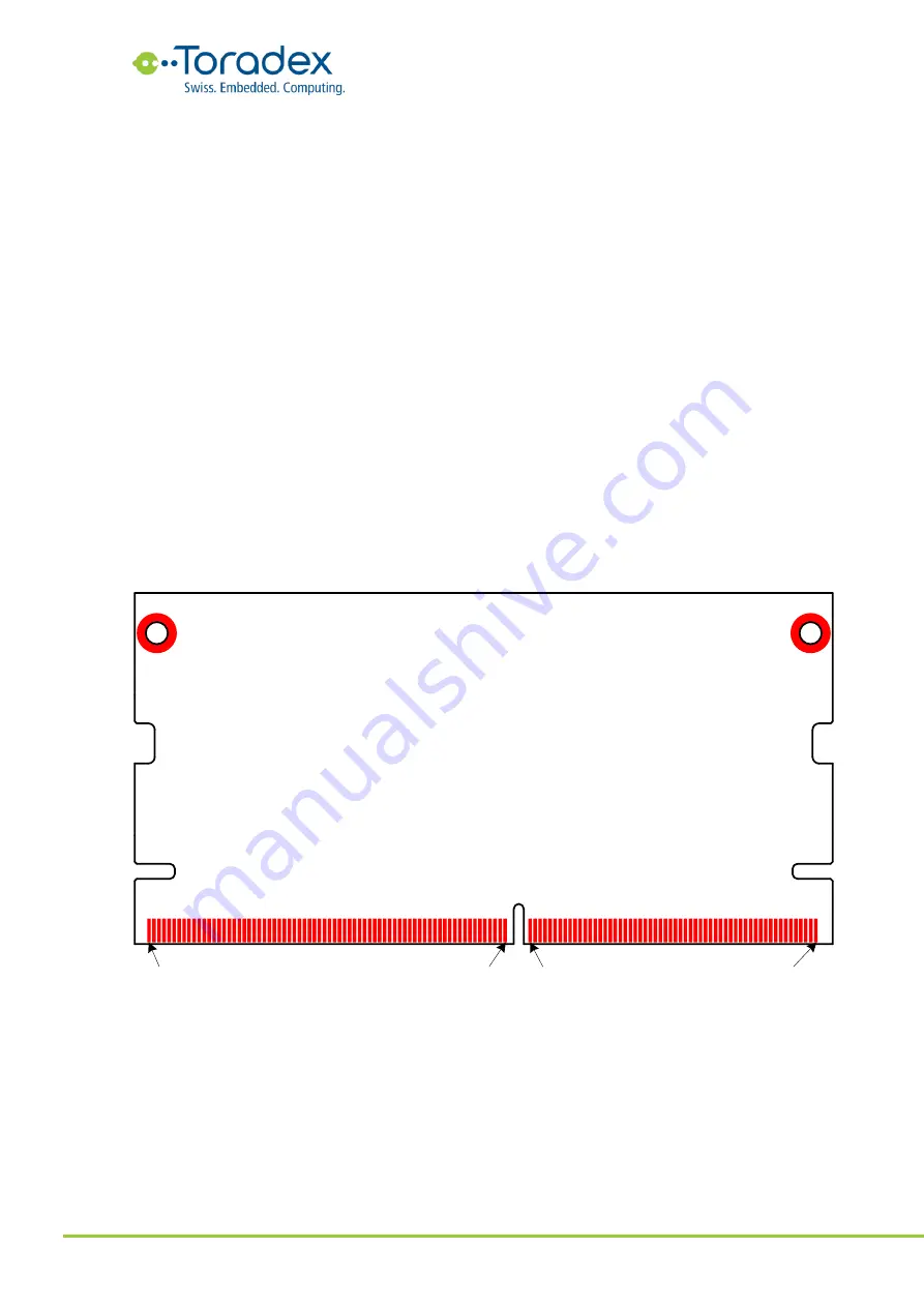
The Verdin module follows the same pin numbering scheme as the SODIMM DDR4 standard. Pins
on the top side of the module have an odd number while the pins on the bottom side have an
even number.
Figure 1: Pin numbering schema on the top side of the module (top view)
Pin 259
Pin 143
Pin 145
Pin 1


