Page 51
slotted holes.
NOTE:
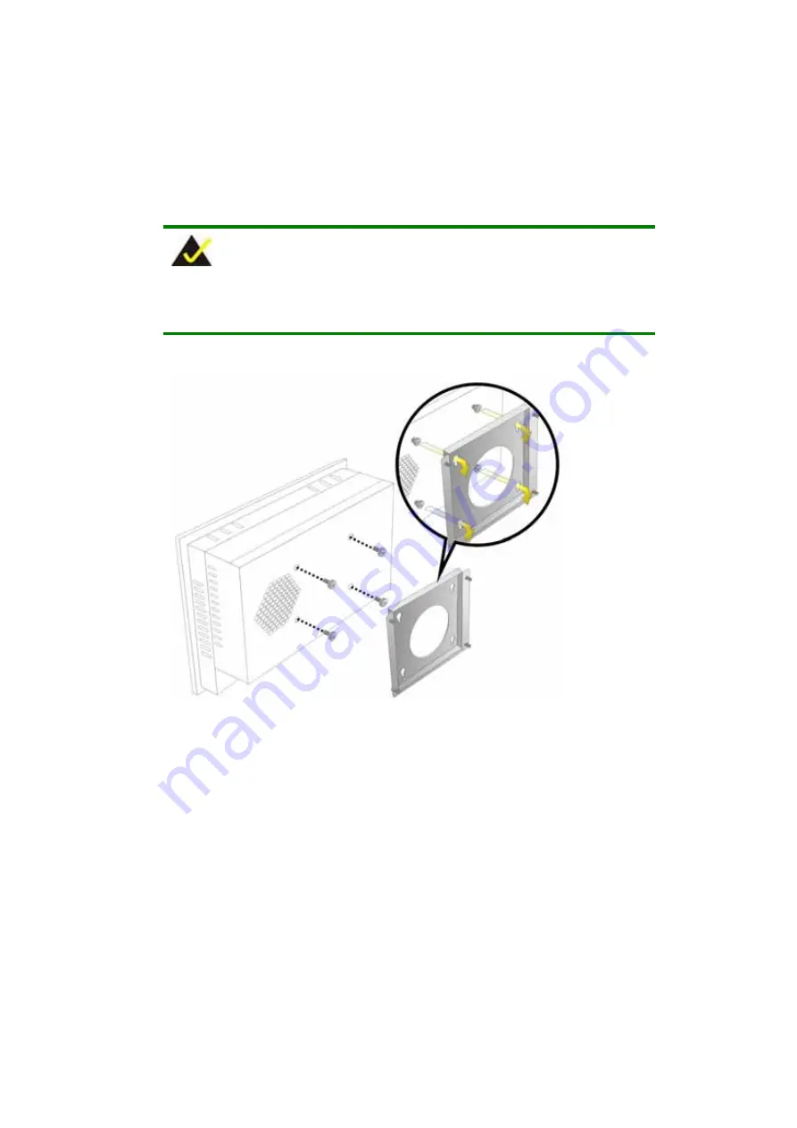
In the diagram below the bracket is already installed on the wall.
Figure 3-12: Mount the Chassis
Step 3:
Secure the panel PC with the wall-mounting kit. To do this, stick the protective
cushion to the wall-mounting kit first. Then, put the wall-mounting kit on the top
panel of the panel PC. Carefully mark the location of the wall-mounting kit screw
holes on the wall. Drill a pilot hole at the marked location on the wall. Secure the
wall-mounting kit to the wall by inserting a retention screw into the pilot hole on
the wall (
Figure 3-13
). This step is to avoid the panel PC being pushed apart
Summary of Contents for EX-93821
Page 1: ...Page 1 EX 93821 EX 93823 Flat Panel PC...
Page 13: ...Page 13 1 Introduction Chapter 1...
Page 27: ...Page 27 2 Motherboard Chapter 2...
Page 35: ...Page 35 3 Installation and Configuration Chapter 3...
Page 59: ...Page 59 4 Gasket Replacement Chapter 4...
Page 61: ...Page 61 5 AMI BIOS Setup Chapter 5...
Page 98: ...EX 93821 EX 93823 Flat Panel PC Page 98 3 3 V 12 V VBAT V 5VSB V...
Page 99: ...Page 99 A Safety Precautions Appendix A...
Page 103: ...Page 103 B BIOS Configuration Options Appendix B...
Page 107: ...Page 107 C Software Drivers Appendix C...
Page 116: ...EX 93821 EX 93823 Flat Panel PC Page 116 THIS PAGE IS INTENTIONALLY LEFT BLANK...
Page 117: ...Page 117 D Hazardous Materials Disclosure Appendix D...
Page 121: ...Page 121 E Index...


