EX-93821/EX-93823 Flat Panel PC
Page 50
Step 2:
Carefully mark the locations of the four bracket screw holes on the wall.
Step 3:
Drill four pilot holes at the marked locations on the wall for the bracket retention
screws.
Step 4:
Align the wall-mounting bracket screw holes with the pilot holes.
Step 5:
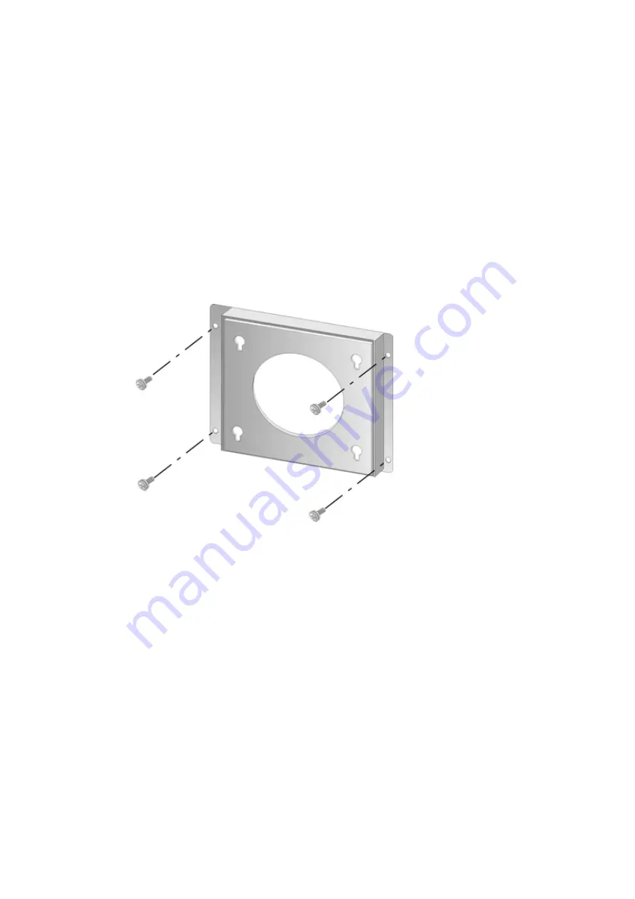
Secure the mounting-bracket to the wall by inserting the retention screws into
the four pilot holes and tightening them (
Figure 3-11
).
Figure 3-11: Wall-mounting Bracket
Step 6:
Insert the four monitor mounting screws provided in the wall mounting kit into the
four screw holes on the real panel of the monitor and tighten until the screw
shank is secured against the rear panel (
Figure 3-12
).
Step 1:
Align the mounting screws on the monitor rear panel with the mounting holes on
the bracket.
Step 2:
Carefully insert the screws through the holes and gently pull the monitor
downwards until the monitor rests securely in the slotted holes (
Figure 3-12
).
Ensure that all four of the mounting screws fit snuggly into their respective
Summary of Contents for EX-93821
Page 1: ...Page 1 EX 93821 EX 93823 Flat Panel PC...
Page 13: ...Page 13 1 Introduction Chapter 1...
Page 27: ...Page 27 2 Motherboard Chapter 2...
Page 35: ...Page 35 3 Installation and Configuration Chapter 3...
Page 59: ...Page 59 4 Gasket Replacement Chapter 4...
Page 61: ...Page 61 5 AMI BIOS Setup Chapter 5...
Page 98: ...EX 93821 EX 93823 Flat Panel PC Page 98 3 3 V 12 V VBAT V 5VSB V...
Page 99: ...Page 99 A Safety Precautions Appendix A...
Page 103: ...Page 103 B BIOS Configuration Options Appendix B...
Page 107: ...Page 107 C Software Drivers Appendix C...
Page 116: ...EX 93821 EX 93823 Flat Panel PC Page 116 THIS PAGE IS INTENTIONALLY LEFT BLANK...
Page 117: ...Page 117 D Hazardous Materials Disclosure Appendix D...
Page 121: ...Page 121 E Index...