background image

13


Start

-

up Procedure


Before the 

WOW RO System 

is operational, it must be properly primed by removing all air from 

the unit. 


Purging the system:


A.


Make sure the RO faucet and all other outlets using an isolation valve are CLOSED.


B.


Turn feed water adapter Valve and emergency shut

-

off valve on.  Notice the sound of water 

filling the system.


C.


Within 3

-

4 minutes, the waste line from the system will open with a noticeable exhaust of air 

and water.


D.


After waiting another minute, open RO faucet.  Notice air/water exhausting from faucet port.  
Wait for a steady stream of water and then CLOSE the faucet.


E.


Within 2 minutes, the waste port will open again with a shot of air/water exhausting.  At this 
point, let the tank fill for approximately 45 minutes.


F.


After system shuts down (indicated by no audible or visible drain flow), open RO faucet and 
empty system to a trickle.  At this point, the system should have generated a full gallon and a 
half of water.  If not, see Note 1 below or refer to Troubleshooting Guide (Page 35). 


G.


Turn off RO faucet and let water make

-

up process refill tank (approximately 45 minutes). 


H.


The unit is operational, but it is required to repeat this process (Steps F & G) five times to com-
pletely prep and flush filter cartridges and ensure TDS levels are at their minimums.  This will 
guarantee the best tasting water immediately.


I.


System is now fully operational!  If system does not work, refer to Troubleshooting Guide. 


Note  1:    If  your  connections  along  any  FA  lines  have  a  leak  (even  one  drop),  the  system 


will not work.  Repair leak and repeat Start

-

up Procedure.


Note 2:  See Pages 15

-

21 if adding any appliances.


Note 3:  Unlike traditional captive air RO systems, the WOW RO System will always have 


water in the tank. This fact does not change the need to follow Steps A

-

F for start

-

up.


Step 5


Installation Steps and Start

-

Up Procedures


Summary of Contents for WOW RO System

Page 1: ...ER MANUAL for Undercounter WOW RO Systems 23880 Madison Street Torrance CA 90505 310 375 5000 www wowwater com V13 2 12 18 Powered by Scan with QR Reader App Visit our website www wowwater com Place D...

Page 2: ...mix drinks fill batteries etc with treated water Caution The working capacity of this appliance depends on the pressure and temperature of the water supply This appliance is not guaranteed to work pro...

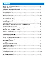
Page 3: ...tem 14 Connecting to Multiple Appliances 15 Refrigerator Ice maker Coffee maker Cooler setup 16 21 Section 3 When More Water is Needed 22 Adding Extra Storage Tanks 23 Modular Expandability 24 Section...

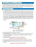
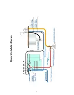
Page 4: ...4 Figure 1 Installation Diagram...

Page 5: ...5 Section 1 Installation Start up Procedures...

Page 6: ...ed outlets Without an isolation valve the WOW RO System will not start Refer to Section 2 for connecting additional appliances 5 Before beginning Start up Procedures Step 5 Page 13 make sure all tube...

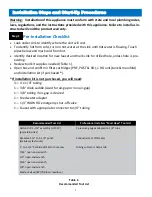
Page 7: ...d confirm 3 filter cartridges PRE POST RO 1 RO unit tank manifold and installation kit if purchased If installation kit is not purchased you will need 3 4 x 1 4 tubing 1 3 8 drain saddle sized for air...

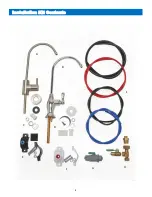
Page 8: ...8 Installation Kit Contents A B C D E F G H I G...

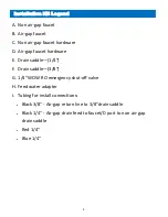
Page 9: ...E Drain saddle 1 4 F Drain saddle 3 8 G 1 4 WOW RO emergency shut off valve H Feed water adapter I Tubing for install connections Black 3 8 Air gap return line to 3 8 drain saddle Black 1 4 Air gap d...

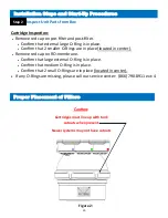
Page 10: ...in place located in center Remove red cap on RO membrane Confirm that large external O Ring is in place Confirm that medium O Ring is in place Confirm that 2 small O Rings are in place located in cent...

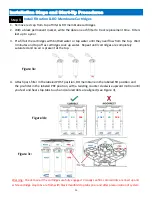
Page 11: ...d and no air is present at the top 4 Attach post filter in the labeled POST position RO membrane in the labeled RO position and the pre filter in the labeled PRE position with a twisting counter clock...

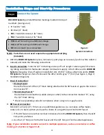
Page 12: ...and the other end to gray F port See Figure 1 Page 4 Installation Diagram C Drain D connection i Air Gap Faucet Route the free end of the 1 4 black tubing attached to the RO faucet air gap to the conn...

Page 13: ...pen RO faucet and empty system to a trickle At this point the system should have generated a full gallon and a half of water If not see Note 1 below or refer to Troubleshooting Guide Page 35 G Turn of...

Page 14: ...ottles ex ceeding 1 gallons at same time additional storage will be required In addition devices with larger storage capacities like coolers will require greater draw down needs Draw down refers to am...

Page 15: ...ll additional outlets C Charge system to its full status refer to Start up Page 13 D Follow the instructions provided from Pages 16 22 Determining Your Expansion and Storage Needs A standard WOW RO Sy...

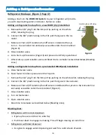
Page 16: ...g Lines Adding a refrigerator hook up from a pre installed WOW wet installation a Close feed water valve b Open faucet to relieve pressure on the FA ports c Remove the 3 8 plug from the FA1 port by pu...

Page 17: ...17 Figure 7 Refrigerator Icemaker...

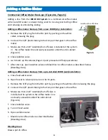
Page 18: ...ion valve e Go to Start up Procedures Page 13 and proceed until fully operational f After start up open isolation valve and bleed line to coffee maker as described below Bleeding Lines Adding a coffee...

Page 19: ...Close isolation valve e Go to Start up Procedures Page 13 and proceed until fully operational f After start up open isolation valve and bleed line to cooler as described below Bleeding Lines Adding a...

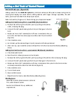
Page 20: ...isolation valve e Go to Start up Procedures Page 13 and proceed until fully operational f After start up open isolation valve and bleed line to hot tank as described below Bleeding Lines Adding a hot...

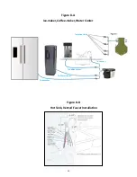
Page 21: ...21 Figure 8 A Ice maker Coffee maker Water Cooler Figure 8 B Hot Tank Vented Faucet Installation Isolation Valve To Faucet To Water Cooler To Coffee Maker To Icemaker...

Page 22: ...dard WOW RO System holds 1 gallons The WOW RO System has been de signed in a modular format to add additional storage tanks as needed Review chart below for each device connected Add all additional ta...

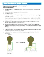
Page 23: ...ed to the spare tank See Figure 9 below for one or multi ple tank set ups f Connect green tubing between the matching PW ports on the manifold and the adapter See Figure 9 below for one or multiple ta...

Page 24: ...24 Modular Expandability Parallel Processing...

Page 25: ...25 Section 4 Plumbing the Sink...

Page 26: ...ction of the drain saddle See Figure 11 D Make sure to align the drain saddle to the drilled hole use small screwdriver to check align ment E Attach the drain saddle to the drain pipe and tighten the...

Page 27: ...ructions Drilling a porcelain clad steel or cast iron sink Caution Be careful when the drill is about to penetrate the base metal of the sink Reduce the speed and support the drill so the drill chuck...

Page 28: ...Reconnect the riser tube to the other end of the incoming water supply valve Do not overtighten Caution A longer riser tube assembly will be required if a gentle loop cannot be made See Figure 13 E F...

Page 29: ...29 Section 5 Maintenance...

Page 30: ...er cartridges 2 With a black permanent marker write the date on each filter to track replacement time Filters last up to a year in most cases 3 Pre fill all cartridges with bottled water or tap water...

Page 31: ...d filters should be replaced depends upon the quality of the water that enters the appliance Contact your WOW Water specialist or visit www wowwater com for replacement filters and parts Note The inst...

Page 32: ...the WOW RO system This low energy technology significantly reduces nearly every category of undesirable water contaminants as small as 1 100 000 000 one hundred millionth of an inch This includes ino...

Page 33: ...gen Per oxide inside This is important 6 Place tubing in the SQ port and direct SQ exit into a bucket or pot 7 Using the supply line to pressurize the sanitizer is best so detach from the F port Place...

Page 34: ...asing Reverse Osmosis A Practical Application Manual for Residential Point of Use Systems by Robert Slovak one of the members of the TOPPER development team This publication can be purchased directly...

Page 35: ...35 Section 6 Troubleshooting...

Page 36: ...water is needed Sec tion 3 Page 22 Water dispensing does not meet average flows Not enough water pressure Pre filter is plugged House regulator may need to be increased or add a pump Change filter Se...

Page 37: ...change post filter Match filter with proper position on RO unit Change post filter Water leaking from Air Gap installa tion Air gap installation incorrect Clogged drain Remove loops or sags from Air G...

Page 38: ...ecom mended to use only microbiological safe water with your WOW RO System appliance Caution Do not use water that is microbiologically unsafe or of unknown quality without adequate disin fection befo...

Page 39: ...are not covered by this warranty We assume no warranty liability in connection with this Reverse Osmosis System other than as specified herein This warranty is in lieu of all other warranties expresse...

Reviews: