background image

28

Using the Front Panel


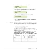
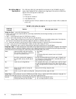
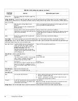
SymRate

sets the current transmission symbol rate

1.0 to 20.0 MSps
default: 5.500187 MSps

Additional Information: The symbol rate is the number of symbols required to transmit the data stream over a satellite link using 
quadrature phase shift keying (QPSK).
The symbol rate is automatically calculated based on the modulator input transport stream data rate, the Viterbi code rate, and 
other fixed parameters that add overhead to the data stream.
If the displayed symbol rate exceeds the allowable satellite bandwidth, the data will be corrupted during transmission.
To determine the satellite bandwidth required to transmit the displayed symbol rate, use the following equation:

Symbol Rate x 1.35 = Required Satellite Bandwidth (in Hz)

Mod Source

selects the modulator input 

!

ASI - uses the input from the ASI IN connector 

!

internal - uses the TE3000 backplane as source (default)

Tx Power-up

sets the transmit carrier restore mode

!

off – following power-up or reset, the modulator output is disabled 
regardless of the modulator output carrier state prior to the power-up or 
reset. 

!

restore – following power-up or reset, the modulator output is restored to 
the state that was stored in non-volatile memory just prior to the power-up 
or reset. (default)

Mod Status 

query-only; displays if the modulator is locked to 
the incoming signal

!

locked – modulator is locked onto the incoming signal

!

unlocked – modulator is not locked onto the incoming signal

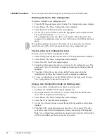
Config>Service # Menu — Used to setup and configure the TE3000 Video, Audio, and Data services

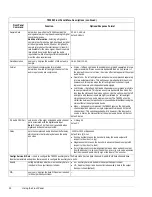
Config>Service # >Setup — Used to setup and query TE3000 services and service providers.

Service ID

assigns a number to a service, which, in 
combination with the Service and Provider names, 
allows the user at the decoder site to select a 
service 
Additional Information: If the Service ID is 
changed, the TE3000 automatically sets the 
Service ID or Program Number within the Event 
Information Table, Program Map Table, and Service 
Description Table to the same number. The Service 
ID may also be referred to as the Program Number. 

!

if DVB: 1 to 231; default: 1

!

if ATSC: 2 to 231; default: 2

Name

query-only; displays the name of the service

text string
if default configuration is:

!

DVB, default is: service 1

!

ATSC, default is: ch2

Provider

query-only; displays the name of the provider when 
DVB or MPEG tables are enabled
Note: Provider is only available when 
System>Table Type is set to DVB or MPEG.
This parameter can be set using a remote terminal 
and the appropriate remote command.

text string
default: unnamed

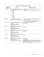
Major Channel

sets the major channel when ATSC table types are 
enabled
Note: Major Channel is only available when 
System>Table Type is set to ATSC.

1 to 99
default: 30

Minor Channel

sets the minor channel when ATSC table types are 
enabled
Note: Minor Channel is only available when 
System>Table Type is set to ATSC.

1 to 99
default: 2

TE3000 Front Panel Menu Descriptions  (continued)

Front Panel 

Command

Function

Options/Response Format

Summary of Contents for TE3000

Page 1: ... Radyne ComStream Company 6340 Sequence Drive San Diego California 92121 phone 858 587 0252 fax 858 587 0257 TPN 505 010690 0001 Rev C 07 02 01 TE3000 MPEG 2 DSNG Encoder Installation and Operation Guide ...

Page 2: ...icted Rights JUNE 1987 clause at FAR 52 227 19 as applicable Manufacturer is Tiernan Radyne ComStream Inc 6340 Sequence Drive San Diego CA 92121 USA Contents of this manual are provided as is without warranty of any kind either expressed or implied including but not limited to the implied warranties of merchantability fitness for a particular purpose and non infringement Content could include tech...

Page 3: ...A and B Ports 9 Remote Unit Connections 12 DTE DCE Switch 14 Fault Relay 14 Transport Connection Ports 15 Modulator Output to Upconverter Connections 16 Chapter 3 Using the Front Panel 17 Front Panel Components 17 Navigating Through the Menus 19 LCD Display 19 Front Panel Navigation Buttons 20 Issuing Commands 23 Modulator Control Buttons 25 Front Panel Menu Descriptions 26 TE3000 Procedures 38 Ch...

Page 4: ...ational Problems and Possible Solutions 81 Chapter 7 Maintenance and Software Upgrades 83 Appendix A Technical Specifications 85 Appendix B IF Looptest 87 Required Equipment 87 Setting Up the TE3000 87 Powering the Equipment 88 TE3000 Looptest Configuration 88 IRD Looptest Configuration 90 Performing the IF Looptest 90 Testing the TE3000 Operational Features 90 Appendix C TE3000 PID Assignments 91...

Page 5: ...se icons are The hazard icon identifies the possibility of electric shock when you perform an operation with the TE3000 or if you do not use the TE3000 according to instructions The caution icon identifies information that requires careful attention in order to prevent equipment damage and or injury to the operator The note icon identifies information for the proper operation of your equipment inc...

Page 6: ... select Control Clock Date June 03 2003 means From the control menu select clock From the clock menu select date At the date option enter the date June 03 2003 in the correct format Displays The system may return values and messages on a front panel LCD remote terminal or both In this manual these values and messages appear in a different type date 06 23 2003 restore default1 Revision History This...

Page 7: ...all Tiernan Customer Service Cartons and Packing Materials The factory shipping carton and packing materials are designed to protect the equipment from excessive shock and vibration that can occur during shipping Use the original shipping carton and packing materials to repack the unit for shipment to another location or to return the unit to Tiernan for repair For additional information on equipm...

Page 8: ...position of the TE3000 Never place the TE3000 on a soft surface that would obstruct the required airflow into the ventilation slots Use Correct Power Source For units equipped with a North American power cord the cord has an IEC compatible female plug on one end and a male plug on the other end This cord is UL and CSA approved up to 1 25VAC at 10 A and is ready to use with no user wiring required ...

Page 9: ...ver put any object including your fingers through slots or openings as this could result in touching dangerous voltage points short circuiting parts electric shock or fire There are no user serviceable parts inside the TE3000 If an object falls into the equipment unplug the unit and contact Tiernan Customer Service as serious damage could occur to the TE3000 or its components Use Approved Attachme...

Page 10: ...viii Preface ...

Page 11: ...horizontal resolutions Supports compressed audio rates of 64 to 384 kbps and four different audio channel compression methods Accepts two high speed independently programmable auxiliary data channels Automatic configuration of video and audio rates to match the available transmission bandwidth for optimum performance Dedicated modulator control buttons are provided on the front panel for one touch...

Page 12: ... operate in point to point or point to multipoint transmission applications The TE3000 accepts all commonly used video and audio input formats and outputs an MPEG 2 DVB compliant transport stream in addition to a DVB compliant QPSK modulated 70 MHz IF carrier If an external transport stream is provided from another encoder the TE3000 will multiplex the two transport streams to form a combined tran...

Page 13: ... The TE3000 has a number of default configurations that can be restored as well as numerous user defined configuration sets that can be saved and restored Construction The TE3000 is a small 2RU 90mm 3 15 high 21 inch rack mount chassis with an international auto sensing AC power supply Network Management Software To simplify and centralize equipment control Tiernan offers a variety of Network Mana...

Page 14: ...4 TE3000 Overview ...

Page 15: ...the equipment to allow easy access to the rear panel and provide adequate ventilation To properly install the TE3000 follow the instructions provided in the appendix on table top and rack mount installation instructions Ventilation The TE3000 must be positioned to receive adequate ventilation at all times The cooling fan pulls air in through the side vents circulates the air and exhausts it out th...

Page 16: ...the TE3000 rear panel 4 Connect the male plug of the AC power cord to an external A Cpower conditioning surge suppressor 5 Connect the AC power conditioning surge suppressor to an A Coutlet Corrupted AC input power can interrupt TE3000 operations and cause permanent damage to the unit You should purchase and install a commercially available external AC power conditioning surge suppressor to protec...

Page 17: ...f the composite video in signal on a female BNC connector This connector should be terminated with a 75Ω load to maintain proper video levels through the system Analog GenLock The Analog GenLock is a female BNC connector with 75Ω impedance The 27 MHz source clock is derived from one of the following sources Incoming video External analog genlock input SMPTE RP154 NTCS EB UD23 and EBU D25 PAL The e...

Page 18: ...he D1 Video GenLock is a female BNC connector with 75Ω impedance The port accepts external SMPTE 259M input When activated the D1 Video GenLock is used as the timing reference for the 27 MHz MPEG system clock of the TE3000 The external genlock input permits the user to hot switch the video input during the vertical blanking interval without losing synchronization Typically GenLock is connected to ...

Page 19: ...pment DTE to the TE3000 you must determine the most effective TE3000 and DTE clock source arrangements There are three different ways to configure the clock interface for the TE3000 and the DTE Clock Interface Configuration 1 is the most reliable clock source arrangement This configuration requires the DTE to provide a clock TT synchronous with the data SD to the TE3000 Clock Interface Configurati...

Page 20: ...e ST to the TE3000 on TT The TE3000 uses TT to latch the data The TE3000 auxiliary data channel must be configured for an external clock source to accept TT from the DTE Clock Interface Configuration 2 If the DTE cannot turn around the ST but has an internal clock source that can be provided as TT to the TE3000 use this option to configure the auxiliary data channel The following block diagram sho...

Page 21: ...lock will be If the internal clock is used to latch the data the length of cable between the DTE and the TE3000 must be limited to one meter 3 feet Additionally the auxiliary data rate must be limited to not more than 64 kbps If the cable length exceeds one meter or if you attempt to process data at rates above 64 kbps the auxiliary data may be corrupted Asynchronous Configuration In asynchronous ...

Page 22: ...The pinouts for the RS 232 port configured as DCE are listed in the following table Aux Data Port Pin Assignments Asynchronous RS 422 Pins Signal Direction Definition 1 Unused In 2 CTS Out Clear to Send 3 RD In Transmit Data 4 RTS In Request to Send 5 GND Ground 6 CTS Out Clear to Send 7 Unused 8 RD Receive Data In 9 RTS In Request to Send RS 232 Port Pin Assignments DCE Pin Signal Direction Signa...

Page 23: ...gement Software NMS program Category 5 UTP patch cable not supplied Connecting to a Network Using the Ethernet Port You can connect the TE3000 to a LAN using the Ethernet port which enables you to monitor and control the TE3000 through a remote unit not directly connected to the TE3000 When connecting the TE3000 to a LAN using Ethernet contact your Information System department to coordinate insta...

Page 24: ...r on using a remote unit DTE DCE Switch The DTE DCE switch is used to change the configuration of the RS 232 port When the port is configured as DCE use a standard cable for the computer Comm port In this configuration the port supports all of the signals required for basic modem support When the port is configured as DTE use a null modem cable to connect the PC to the TE3000 Fault Relay The Fault...

Page 25: ...e TE3000 In this mode the modulator supports transport stream data rates from 1 up to 18 Mbps in SCPC mode depending on the FEC rate selected Output symbol rates range from 1 to 20 MSps MCPC Mode In MCPC mode the ASI output of one TE3000 is fed into the multiplexer of another TE3000 so that the output of the two encoders are multiplexed in a single transport stream The signal from a series of TE30...

Page 26: ...ensures that only the program associated with the failed TE3000 in an MCPC chain of encoders or in a redundant configuration is interrupted by the failure ASI Out Secondary can also be used to monitor the transport stream SMPTE 310 This port is used to output a SMPTE 310 compatible transport stream Mod ASI In Mod ASI In located on the TMOD 6000 is a female BNC connector with 75Ω impedance The port...

Page 27: ...ist of parameters Up and Down buttons used to scroll through parameter options and increase and decrease parameter values Alpha numeric keypad used to enter alphabetic and numeric parameter values Status button hot key which toggles between the current front panel menu and the current faults list Status LED tri color LED alerts you to status and fault conditions Modulator control buttons and LEDs ...

Page 28: ...m Version Firmware firmware version label Hardware version label of installed modules Status Current History list of current faults Relay List Clear List Clear Mod State Code Rate Data Rate Spect Invert Tx Power SymRate Mod Source Tx Power up Mod Status Output Tx Freq Out Mode Slot 1A to 1B Loc TS Enable Loc TS Status ExtRate LocRate New Rename Delete list of configuration sets list of configurati...

Page 29: ...ndicating that the TE3000 is processing information When the asterisk disappears the process is complete Equal Sign Most parameters though not all can be modified in order to configure the TE3000 Configurable parameters are followed by an equal sign denoting that the parameter can be modified Colon There are some parameters that are automatically set for your system or that are query only paramete...

Page 30: ... additional current faults Front Panel Navigation Buttons The following front panel buttons are used to move through menus in order to issue commands and view status and fault information Right and Left Butto ns The Right and Left buttons are used when either a right or left arrow is displayed on the LCD These buttons move you through the menu structure in the following manner At a menu level thes...

Page 31: ...mand press the Enter button to execute the command To set a parameter option such as a new video frame rate press the Enter button The TE3000 is configured with the new parameter value The new values are then stored in nonvolatile memory Exit Button The Exit button moves you through the menu structure in the following manner At a menu level the Exit button moves you up one menu level If you are at...

Page 32: ...meric field the following alphabetic and numeric characters are displayed when a key is pressed The first press of a number key displays the first character in the set sequential presses of the same key advance through the set in a circular fashion The cursor is advanced by either pressing another number key or by pressing the right arrow key For example to enter the word ALL which has two charact...

Page 33: ...y on the keypad this toggles the value between negative and positive Status Button The Status button is a hot key which enables you to immediately view any faults currently occurring on the TE3000 and then toggle back to the front panel menu on which you were working Issuing Commands To issue a command from the front panel perform the following steps 1 Navigate to the required command or parameter...

Page 34: ...thout modifying it by pressing either the Exit button which returns you to the previous menu level Left or Right buttons which take you to the next parameter In either situation the TE3000 will ignore any values entered and return the parameter to its original setting After Pressing the Enter Button If you accidentally issue an incorrect parameter value to the TE3000 you can correct the error by 1...

Page 35: ...full power CW constant wave Modulate on full power modulated A blinking LED indicates that the button is busy implementing its command When the command is executed the LED stops blinking Command execution takes 5 to 10 seconds to complete Each time you press the button even if the LED is blinking the command is executed The purpose of the buttons is to allow fast and simple operation of the encode...

Page 36: ... sets manage the user defined list and then re initialize the TE3000 using either your user defined configuration sets or predefined factory default configuration settings These configuration sets are not altered by reset power cycling orfactoryDVB default setting of the encoder Restore initializes the TE3000 using either predefined factory configuration parameters or the selected user stored site...

Page 37: ...ip between the selected code rate and the data stream prior to modulation and an indication of the degree of error correction provided by each code rate is shown below Viterbi Code Rate Transport Stream Data Rate Error Correction 1 2 Increases by a factor of 2 100 increase Maximum 2 3 Increases by a factor of 1 5 50 increase Very High 3 4 Increases by a factor of 1 33 33 increase High 5 6 Increase...

Page 38: ...ing signal unlocked modulator is not locked onto the incoming signal Config Service Menu Used to setup and configure the TE3000 Video Audio and Data services Config Service Setup Used to setup and query TE3000 services and service providers Service ID assigns a number to a service which in combination with the Service and Provider names allows the user at the decoder site to select a service Addit...

Page 39: ... format and configures the video mode to match default PAL 625 linePAL N mode NTSC 525 line NTSC mode NTSC 0SU no pedestals NTSC0SU mode Resolution selects the picture resizing that the TE3000 performs prior to video encoding 720 704 544 480 352 default 720 Additional Information As shown in thefollowing table the number of lines depends upon whether the video format is set to NTSC or PAL Resoluti...

Page 40: ...rce This parameter is available only when the video input source is set to analog video input video input is used for the encoder timebase default gen lock genlock input is used for the encoder timebase Input video must be synchronized to Genlock input in order for this option to work properly Delay sets the compressed bit stream buffer delay which controls the time delay between the audio and vid...

Page 41: ... included in the output transport stream Compression sets the output compression format for the audio stream MPEG default MPEG Source sets the source of the audio If digital audio AESEBU D1 embedded audio If analog audio analog Note for embedded audio Config Service Video Input Source must be set to digital Config Service Audio must be set to digital and Config Service Audio Source must be set to ...

Page 42: ...etween the two channels to save bandwidth without losing the stereo effect at the output audio device Mono during audio compression the TE3000 ignores the right audio channel input and produces a single output waveform based on the left channel input This option saves bandwidth however if the input audio source is stereo the stereo effect at the output audio device will be lost default stereo D1 A...

Page 43: ... character length for the asynchronous auxiliary data channel Note Data Bits is only available when Service Data Comm Mode is set to asynchronous 7 8 default 8 Parity sets the parity for the asynchronous auxiliary data channel Note Parity is only available when Service Data Comm Mode is set to asynchronous none even odd default none Stop Bits sets the number of stop bits for the asynchronous auxil...

Page 44: ...lock reference parameters Delay used to compensate for decoder buffering issues 1000 to 1000 milliseconds default zero 0 msec If the decoder s buffer overflow increase the PCR delay If the decoders buffer underflow decrease the PCR delay Transmit Rate sets the transmit rate of the PCR packet 0 to 100 Hz Config Tx Strm Menu Enables you to set and query the TE3000 transport stream system configurati...

Page 45: ... is only available when Tx Strm Mode is set to MCPC enable default disable Loc TS Status query only displays the status of the locally generated transport stream Note Loc TS Status is only available when Tx Strm Mode is set to MCPC locked unlocked LocRate sets the default ratefor the locally generated transport stream Note LocRate is only available when Tx Strm Mode is set to MCPC 1 to 70 Mbps def...

Page 46: ...eset resets the TE3000 to the last configuration set reloads all programmable logic and firmware restarts the unit and clears the fault history log Additional Information As an aid to troubleshooting the fault history log should be reviewed and recorded before resetting or turning the TE3000 power off returns to SD Encoder main menu after reset Control Clock Used to set the date and time Date sets...

Page 47: ...ault relay Current queries the current faults log displays current faults also displays the fault number along with the total number of faults in the current fault log History queries and clears the fault history log list displays fault history log faults are date and time stamped also displays the fault number along with the total number of faults in the fault history log clear clears the fault h...

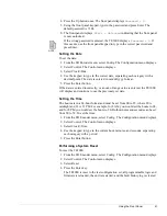
Page 48: ...plays 3 Select New The New Preset menu displays 4 Using the alpha numeric keypad enter a name for the configuration set The name can be up to 15 characters in length and must begin with an alphabetic character 5 Press Enter When the system returns to the Presets menu when the configuration label has been entered into the configuration database 6 To save a configuration set under this label follow ...

Page 49: ... alphanumeric keypad Press Enter When the information is processed the unit returns to the Enter Name menu 7 When you have finished adding IRDs to the Conditional Access list press Exit to return to the main CA IRD menu Viewing the IRD Conditional Access List To view the IRD Conditional Access list 1 From the SD Encoder menu select Config The Configuration menu displays 2 Select CA The Conditional...

Page 50: ...ss Enter The LCD will display Delete IRD name Yes No 7 Ensure that the correct IRD name is displayed and selectYes 8 Press Enter When the information is processed the system returns to the IRD Delete menu Configuring the Encoder for Embedded Audio To configure the encoder for embedded audio the following parameters must be set Config Service Video Input Source must be set to digital Config Service...

Page 51: ...t of range value is entered the TE3000 will display and continue to use the previously set date Setting the Time The hours are in a 24 hour format and must be set from 00 to 23 where 00 is midnight and 23 is 11 PM For example for 8 AM you would set the hours to 08 and for 8 PM you would set the hours to 20 Both minutes and seconds can be set from 00 to 59 To set the time 1 From the SD Encoder menu...

Page 52: ...42 Using the Front Panel ...

Page 53: ...he last changes saved to flash memory Once the configuration is saved using the CM SAVE command the TE3000 automatically restores the saved settings when the unit is reset or powered up Configuring the Remote Control Software Parameters After you have cabled the remote unit to the TE3000 perform the following steps to complete your installation 1 Configure the communications software parameters of...

Page 54: ...esponses more easily 1 From a remote unit launch Telnet by typing TELNET at the command prompt To access the command prompt select the MS DOS Prompt 2 From the Connect menu select Remote System The Remote System dialog box appears 3 At the Host Name or IP Address option type the TE3000 IP address For the procedure used to assign an IP Address refer to the installation chapter 4 For Port Type enter...

Page 55: ...cute commands direct the TE3000 to perform a specified action such as changing a configuration parameter Query commands direct the TE3000 to display the current setting of a specific parameter or to display current status information All commands consists of a command mnemonic which is followed by a space and the command instruction The TE3000 uses the following command mnemonics to group various ...

Page 56: ...BAUD 1200 and press Enter In this example The command mnemonic is MC followed by a space The command instruction is BAUD followed by a space The parameter is 1200 Query commands are issued by typing the command without a parameter and pressing Enter The TE3000 responds to the query by displaying information on the remote display For example to query the remote port baud rate issue the command MC B...

Page 57: ...io bit rate to 256Kbps for analog audio port A issue the command AE 1 A BR 256 typed as follows AE 1 A space BR space 256 To include audio in the transport stream for both digital ports issue the following two commands AE 4 A Enable On enables serial digital audio AE 4 B Enable On enables serial digital audio Typing Remote Commands Remote commands are not case sensitive Commands may be entered in ...

Page 58: ...he command using the proper syntax and format ERROR BAD_RESOURCE_ CONTROLLER_TYPE The command mnemonic is incorrect Use the command to view the current command mnemonics Issue the command using the proper syntax and format ERROR COMMIT_ERROR While attempting to set a command the TE3000 may have entered an inconsistent state and may have an integrity error Reset the command to a known valid state T...

Page 59: ...r ERROR TOO_SMALL The parameter s numeric value is too small Issue the command using the correct parameter Error Message Explanation Action Required Remote Question Mark Commands Response Lists all available command mnemonics associated with the current version of code installed on the TE3000 mnemonic slot port For example AE 1 A Lists all commands associated with that mnemonic mnemonic slot port ...

Page 60: ...ion time stamp affects the synchronization between the audio and video Positive numbers cause the decoder to delay the audio output with respect to the video i e lag Negative numbers cause the decoder to advance the audio output with respect to the video i e lead Zero 0 represents nominal alignment between video and audio output from the decoder i e lip sync In addition a zero value assumes that t...

Page 61: ...RC Front panel command equivalent Config Service Data Comm Mode AXD slot port PARITY N O E N Sets the parity bitfor asynchronous serial communication Parameters are N none O odd E even Front panel command equivalent Config Service Data Parity AXD slot port SRC INT EXT INT Sets the clock source for the synchronous auxiliary data channel parameters are INT internal uses ST to latch the data EXT exte...

Page 62: ... SAVE_CFG SD MCPC Caution Any configuration parameters previously saved under a specified label are overwritten and lost when a new configuration set is saved to the same location Front panel command equivalent Config Presets Save FM CURR_LIST Query only command displays all currentfaults Front panel command equivalent Status Current FM LOG_CLR Clears the fault history log Note Clearing the fault ...

Page 63: ...nel command equivalent Config Control Clock Date MC DUPLEX Half Full Full Sets the duplex operation for the RS 232 remote control port configuration Front panel command equivalent none MC DV Displays the firmware version of all cards in the unit Front panel command equivalent Version Firmware MC FLOW Soft Hard Soft Sets the remote control port flow control Parameters are Soft Software XON XOFF Har...

Page 64: ...s saved to flash memory are restored If the TE3000 configuration is changed using a remote unit an operational test should be performed to verify system operations Then the new configuration should be saved by issuing the CM SAVE command Once the configuration is saved the TE3000 automatically restores the saved settings when the unit is reset or powered up Note The TE3000 real time clock includes...

Page 65: ...The data rate you enter is a function of the symbol rate and the code rate The data rate may be entered directly by issuing a MOD DR command or may be computed based upon the symbol rate you enter Specifically the data rate is equal to the Symbol Rate x 2 x 188 204 x V where V the Viterbi code rate Front panel command equivalent none MOD SI Inverted Normal Normal Spectrum Inversion used to set the...

Page 66: ... situations the modulator should return to a modulated carrier following power restoration Front panel command equivalent Config Output Tx Power up MOD TEMP Query only command displays the current temperature of the modulator in Celsius Front panel command equivalent none MOD TF 52000000 to 88000000Hz in 1Hz increments 70000000Hz Used to set the modulator carrier frequency The acceptable range of ...

Page 67: ...mand equivalent none MUX EXT_LIST Displays the list of active services being received on theexternal input transport stream Front panel command equivalent none MUX EXT_RATE Displays the measured external input transport rate in bps Front panel command equivalent Config Tx Strm ExtRate MUX EXT_STATUS Displays the status of the externally supplied transport stream Responses are Absent no signal Unlo...

Page 68: ...R_HZ 0 4294967295 in Hz 566310000 Hz Sets the carrier frequency when ATSC table types are enabled Front panel command equivalent none TAB MINORCH 1 to 99 2 Sets the minor channel in the ATSC tables Front panel command equivalent Config Service Setup Minor Channel TAB MAJORCH 1 to 99 30 Sets the major channel in the ATSC tables Front panel command equivalent Config Service Setup Major Channel TAB N...

Page 69: ...AB TYPE None MPEG DVB ATSC DVB Controls the type of PSI SI tables to be provided Works in conjunction with the CM Load Def command Front panel command equivalent Config Tx Strm Table Type TAB USR_A_PID where is a valid PIDs 0 Sets the Data A PID to be included in the output transport stream Zero is the default PID Front panel command equivalent none TAB USR_B_PID where is a valid PIDs 0 Sets the D...

Page 70: ...thmic table Front panel command equivalent Config CA Setup Scramble Key TCA UPDATE Loads the active subscriber list from the PGCA database Front panel command equivalent none TCA UR 1 to 60 seconds 15 TCA update rate specifies how often in seconds PGCA information is transmitted VE ATSC_CC On Off Off Configures the encoder to transmit ATSC closed captioning information Parameters are On enables AT...

Page 71: ...rmance maybe adversely affected It is recommended that users consult with Tiernan Customer Service before using the custom configuration Front panel command equivalent Config Service Video Optimize VE port SRC Digital Analog Analog Sets the source of the input video Front panel command equivalent Config Service Video Input Source VE TCC On Off Off Configures the encoder to transmit Tiernan closed ...

Page 72: ...nt panel are restored Any parameter changes made using a remote unit arenot automatically stored in flash memory If the TE3000 is reset prior to issuing the CM SAVE command any changes made using the remote unit will not be restored Instead the TE3000 restores the last changes saved to flash memory When the TE3000 configuration is changed using a remote unit an operational test should be performed...

Page 73: ... panel or remote commands required to change those parameters 5 Configure the TE3000 to the default configuration 6 Configure the TE3000 with any new parameters 7 Ensure that the decoder is correctly configured to operate with the TE3000 parameter settings All TE3000 configuration changes issued from the front panel are automatically save to flash memory Unlike front panel operations TE3000 parame...

Page 74: ...om the SD Encoder main menu select Config 2 The Configuration menu displays Select Presets 3 The Presets Configuration menu displays Select Restore 4 The Restore Preset menu displays The configuration option that appears on the LCD in this example DVB Default is the current TE3000 configuration Even if the current configuration displayed on the LCD is the correct configuration for your requirement...

Page 75: ...mote unit software settings must not be changed before issuing the DVB default command to the TE3000 as the remote unit will not be able to communicate with the TE3000 Configuration Examples All examples presented in this section follow the TE3000 Configuration Procedure presented at the beginning of this chapter and use the DVB factory configuration as the default Configuring a Basic DSNG Setup U...

Page 76: ...settings with the exception of the Audio B channel Step 4 The Audio B channel must be set to Off The front panel menus used to change this parameter are Service Audio Analog AudioB Enable Off Step 5 To configure the TE3000 for this example you must first initialize the unit to DVB default settings The steps to perform this initialization are presented in the previous section Step 6 Once the TE3000...

Page 77: ...ample Step 7 Ensure that the decoder is correctly configured to operate with the TE3000 parameter settings Configuring a Simple SCPC Setup Using the Remote Unit This example configures the TE3000 to a simple SCPC setup Use this example as a guideline substituting your site specific parameter values as required Step 1 In this example assume that the following is a list of your TE3000 operational pa...

Page 78: ...DVB default command CM LOAD_DEF DVB When the remote unit displays the system prompt all of the TE3000 parameters have been set to the DVB default settings 2 If the baud rate setting of the communications package in your remote unit is not set to 38400 bps you must change the baud rate before you can continue When the TE3000 is set to the DVB default setting the remote port baud rate is set to 3840...

Page 79: ...tings Configuring a Simple 2 1 MCPC Setup Using the Front Panel or a Remote Unit This example configures the TE3000 to a simple 2 1 MCPC setup To configure the TE3000s for MCPC operations perform these steps 1 Setup and identify the encoders 2 Calculate the overall output rate requirements for your system 3 Follow the TE3000 Configuration Procedure to configure the encoders and verify MCPC operati...

Page 80: ...transmitted in 1 5MHz of satellite transponder bandwidth A Viterbi FEC rate of 5 6 provides adequate link margin 1 Calculate the symbol rate that fits into the available satellite bandwidth using DVB compliant QPSK spectral mask 15 MHz 1 35 11 11 MSps 2 Use the Viterbi FEC rate of 5 6 to calculate the transport rate that will fit into the available symbol rate 11 11 MSps x 2 QPSK 22 22 Mbps 22 22 ...

Page 81: ...t output rate For the TE3000 2 Multiplexer internally generated transport rate System configuration Modulator input data rate Multiplexer transport output rate Step 4 To change these parameters the following front panel or remote commands can be used Steps 5 and 6 Set the TE3000s to the DVB default settings and issue the following commands to change the required parameters 1 Initialize the TE3000 ...

Page 82: ...t rate using either the front panel Config Output Data Rate value option or the remote command Mux Out_Rate value where value is the calculated total transport output rate 5 If a remote unit was used to set the MCPC configuration parameters issue the CM SAVE command for each TE3000 unit in order to save their configurations to flash memory If you are using a remote unit to perform the TE3000 confi...

Page 83: ...it is operating correctly and has no current faults Yellow current fault is detected Red internal hardware faults are detected or the video or audio encoders are not processing data If the Status LED illuminates yellow or red the Status Button can be pressed which will display the faults listing Refer to the Faults Summary List for a description of the faults and actions to take to resolve the fau...

Page 84: ...it To view current faults using a remote unit issue the FM CURR_LIST command The TE3000 responds with either No Faults if none are present or one or more fault messages For example assume that the input source to the video encoder is interrupted or disconnected To view current faults issue the FM CURR_LIST command The remote unit displays Current Faults LIST 16 25 43 08 21 2001 VI x Loss of Input ...

Page 85: ...and FM LOG_CLEAR Individual faults include a time and date tag The time tag allows you to determine how often a particular event or fault is occurring and to track the performance of internal components The TE3000 maintains an internal run time clock which is used to time tag faults and other events to help you monitor system performance and diagnose problems Viewing Fault History Log on the Front...

Page 86: ... the following information Fault Log at16 25 43 08 21 2001 15 23 17 08 21 2001 VI x Loss of Input 08 57 39 08 20 2001 VI x Loss of Input The query response shows The type of information queried fault log The time the query was issued 16 25 43 The day of the year the query was issued 08 21 2001 A listing of all faults in the fault history log Fault Relay Monitoring The Form C fault relay is a real ...

Page 87: ... problem If the TE3000 did not display an error message during initialization but is not operating properly perform the following diagnostic steps 1 Verify that the unit is configured correctly for your requirements 2 If your system is configured properly but still not operating correctly issue the front panel CONFIG PRESETS RESTORE command or the CM LOAD_DEF remote command to reset the TE3000 to ...

Page 88: ...rations If faults continue check connection ensure input source is in proper format and conforms to specified input levels If unit continues to fail contact Tiernan Customer Service AE x Inp Loss AE x AESEBU Input Loss AESEBU Audio Not Present If unit is functioning normally clear faults and continue operations If faults continue check connections ensure input source is in proper format and confor...

Page 89: ...put MUX x Ext Input Loss TTX External Input Loss Verify input connections Verify external transport stream Ensure input source is in properformat and conforms to specified input levels MUX x Ext Sync Loss MUX x Ext Inp Sync Err TTX External Input Sync Loss Occurs when configuring stack and unit encounters momentary loss of signal If unit is functioning normally clear faults and continue operations...

Page 90: ...ns do not resume contact Tiernan Customer Service VE x Init VE x Init Error Video Encoder Initialization Error Power cycle the unit If normal operations do not resume contact Tiernan Customer Service VE x EncOvrflw VE x ENC FIFO Overflow Video FIFO first in first out Overflow MUX rate is set too low Recalculate all bit rates and enter correct rates or select AUTO mode VE x PesOvrflw VE x PES FIFO ...

Page 91: ...Udrflw VI x FIFO Underflow Analog D1 FIFO first in first out Underflow If unit is functioning normally clear faults and continue operations If faults continue check connections ensure input source is in proper video format and conforms to specified input levels If unit continues to fail reset unit VI x Undflw VI x D1 FIFO Underflow Digital Video D1 Video FIFO first in first out Empty If unit is fu...

Page 92: ...deo input source that is being provided Problem No audio output from the decoder Solutions Verify that the audio cabling to the encoder is correctly connected Verify that the cabling from the decoder to the audio monitor is correctly connected Ensure that the TE3000 is configuredfor the audio input source that is being provided Problem No video or audio output from the decoder Solutions Data link ...

Page 93: ... fan intake grills free of obstruction Field Software Upgrades The TE3000 is controlled by a built in micro controller equipped with a non volatile memory that is used to store configuration settings operational software operational firmware and field programmable gate array FPGA configuration files For instructions on performing a field software upgrade contact Customer Service ...

Page 94: ...84 Maintenance and Software Upgrades ...

Page 95: ...ort stream Timing Program clock reference PCR in the transport layer Presentation time stamp PTS in the PES layer Genlock to either incoming composite video orexternal composite black burst signal Transport Output MPEG 2 DVB compliant transport stream Two DVB ASI outputs 75 Ω BNC connector Single program SCPC transport stream 1 to 25 Mbps Multi program MCPC transport stream 1 to 70 Mbps Transport ...

Page 96: ...86 Technical Specifications ...

Page 97: ...enerator camera audio VTR audio or equivalent Two audio input cables analog or digital ASI coaxial cable BNC Baseband video monitor NTSC PAL or auto detecting Video output cable BNC Baseband audio monitor Audio output cables Modulator output cable to cable the BNC connector output of the modulator to an upconverter Looptest cable with an F type connector to cable the upconverter to an IRD You may ...

Page 98: ...al audio B input connector 6 Cable the ASI Out Primary transport output to the MOD ASI IN 7 Cable the modulated output of the modulator from the TX IF OUT port to the L band upconverter using the modulator output cable 8 Cable the output of the upconverter to the appropriate input port of an IRD using the looptest cable 9 Cable the video and audio outputs from the IRD to the appropriate output dev...

Page 99: ...7 Press Enter 8 Initializing displays for a few seconds 9 When the LCD displays the main menu the TE3000 is set to the default DVB configuration To review the DVB default configuration settings refer to Appendix B Selecting the Video Source Next select the video source which will be used for the test To select a video source 1 From the main menu select Config 2 From the Config menu select Service ...

Page 100: ...Contact Tiernan Customer Service if you need assistance Once the IRD demod decoder and transport functions all display locked continue to the operational fault check section Operational Fault Check To perform an operational fault check perform these steps 1 Clear the fault history memory for both the TE3000 and IRD using the front panel menus 2 Verify that the TE3000 Status LED is illuminated gree...

Page 101: ...io E is base 1000 hex 4096 decimal Audio F is base 1001 hex 4097 decimal Audio G is base 1002 hex 4098 decimal Audio H is base 1003 hex 4099 decimal Auxiliary Data A is base A hex 10 decimal Auxiliary Data B is base B hex 11 decimal For example for a service with a program number of 2 the following PIDs are automatically assigned Program s base PID is 20 hex 2h x 10h 20 hex PMT which equivalent to...

Page 102: ...92 TE3000 PID Assignments ...

Page 103: ... install the rubber feet perform these steps 1 Ensure that there are four rubber feet included in the shipping kit 2 Break the feet apart from one another Working with one rubber foot at a time a Remove the protective backing b Place the foot under one corner of the unit with the sticky side against the unit c Press the foot firmly against the unit When you are finished there should be one rubber ...

Page 104: ...using your own washers and bolts 4 Ensure that the installation provides the minimum required air flow clearances at the sides and rear of the unit Rear Rack Mount Instructions The rear rack mount kit contains the following items Two mounting plates Two rack mount brackets Four mounting plate screws Four connector screws with attached washers Note the 1U ship kit contains eight connector screws Fo...

Page 105: ...T DIGITAL AL AUDIO AUDIO J24 J24 J23 J23 J22 J22 J21 J21 ASI OUT ASI OUT SECONDAR SECONDARY PRIMAR PRIMARY MUX MUX ASI IN ASI IN LEFT LEFT ANALOG NALOG AUDIO 1A AUDIO 1A RIGHT RIGHT J4 J4 AUX DA AUX DATA 3B 3B J1 J11 AUX DA AUX DATA 3A 3A J10 J10 J3 J3 J2 J2 J1 J1 GENLOCK GENLOCK VIDEO IN VIDEO IN VIDEO OUT VIDEO OUT ANALOG ANALOG ETHERNET ETHERNET FAUL AULT RS 232 RS 232 0 Fuse 4A 4A 4B 4B CONTRO...

Page 106: ...quired air flow for safe operation is provided Rack Stability During installation consider weight distribution on the rack hazardous stability conditions may arise if units are loaded into the rack unevenly Input Supply Overloading of supply circuits could impact over current protection and supply wiring To ensure that supply circuits are not overloaded review the nameplate ratings Grounding Relia...

Page 107: ...ransmitted over a given time period See also bps BNC British Naval Connector A type of connector featuring a locking pin on the female end and a cut out groove for the pin on the male end bps A ratio of the number of bits of data transmitted to the number of seconds elapsed expressed as bits per second buffer In data transmission a buffer is a temporary storage location for information being sent ...

Page 108: ...of time that is equal to 0 1 seconds For example 15dsec is equal to 1 5 seconds DTE Data Termination Equipment A generic name for any device that generates information to be transmitted to another device or over a transmission system For example visual display units computers and office workstations DVB Digital Video Broadcast A set of standards providing the specifications for transmission and re...

Page 109: ...ge Used for satellites employing 14GHz on the uplink and 11GHz on the downlink in support of such applications as broadcast TV for man on the street interviews and other situations requiring a small portable dish Ku is also used in Direct Broadcast Satellite DBS systems or Direct Satellite System DSS L band 1 Portion of the electromagnetic spectrum commonly used in satellite applications with freq...

Page 110: ...ier Level 3 155 52 Mbps refer to STM 1 Ohm A unit of measure for resistance symbolized by the Greek letter omega Ω Defined as the electrical resistance between two points of a conductor when a constant difference of potential of 1 volt applied between these points produces in this conductor a current of 1 ampere the conductor not being the source of any electromotive force overhead A number of dat...

Page 111: ...k device hub router bridge etc to the workstation console used to oversee the network The agents return information contained in a Management Information Base which is a data structure that defines what is obtainable from the device and what can be controlled Sps Samples per second A ratio of the number of times that an analog signal is measured and converted to a binary number to seconds elapsed ...

Page 112: ...102 Glossary ...

Page 113: ...ransport stream MCPC mode 15 transport stream SCPC mode 15 control menu 36 current faults 73 viewing on front panel 73 viewing on remote device 74 D D1 video genlock 8 in 8 out 8 data menu 32 date setting 41 default password 41 digital audio input ports 9 down button 22 DTE DCE switch 14 DVB defaults setting 63 E enter button 21 error messages 48 Ethernet port connecting to a network 13 establishi...

Page 114: ...ntrol 13 fault relay 14 Mod ASI in 16 RS 232 control 12 SMPTE 310 16 Tx IF out 16 power cords international applications 6 north american applications 6 power source connecting to 6 power up sequence 6 R remote command descriptions 49 62 issuing 46 listing of 49 syntax 46 types 45 typing 47 remote unit 48 command descriptions 49 command types 45 commands issuing 46 communications overview 45 conne...

Reviews: