


A-3
AppendIX A - InStALLAtIOn cont’d
GETTING.STARTED
Thrane & Thrane
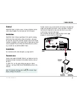
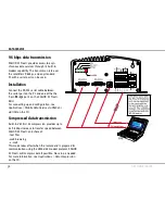
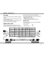
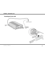
at the BDU
coax cable
A.25.metre.coaxial.cable.type.RG-223.(103154).is.supplied.as.
standard.
For greater lengths, see the table below which lists suitable
double screened coax cables.
The.coax.cable.should.be.secured.by.laying.the.cable.in.a.tube.
and/or.by.fastening.the.cable.to.avoid.damage.
Optional antenna cable
Double.screened.50.ohm.coaxial.cable.must.be.used.for.
connection.between.the.BDU.and.Antenna.Unit..A."pigtail".is.
required.in.each.end.for.the.RF.1/2".50.type.cable.
The.maximum.length.of.the.coax.cable.is.limited.by.the.DC.
and.RF.loss.through.the.cable:
maximum dc loss
:
R.loop.4.0.ohms
minimum/maximum RF attenuation at 1.6 GHz:
4/20.dB
power source
The.equipment.operates.from.11.to.32.Volts.DC..Maximum.
power.consumption:.
transmit mode:
110 W
receive mode (idle):
0 W
Summary of Contents for SAILOR 33 Fleet+
Page 1: ...F77 USER MANUAL SAILOR 33 Fleet Getting Started ...
Page 2: ......
Page 7: ... GETTING STARTED INTRODUCTION cont d SAILOR 33 Fleet Antenna Unit Parts ...
Page 28: ...28 GETTING STARTED HANDSET FUNCTIONS cont d Date 15 March 2007 Satellite Coverage Map ...
Page 29: ...29 GETTING STARTED HANDSET FUNCTIONS cont d Coverage Map for Each Ocean Region ...
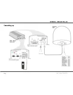
Page 49: ...A APPENDIX A INSTALLATION cont d GETTING STARTED Connecting up ...
Page 50: ...A APPENDIX A INSTALLATION cont d GETTING STARTED Grounding and strain relief ...
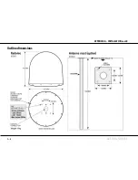
Page 51: ...A APPENDIX A INSTALLATION cont d GETTING STARTED Outline dimensions ...
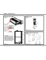
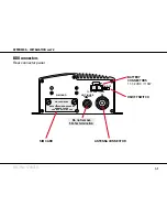
Page 54: ...A APPENDIX A INSTALLATION cont d GETTING STARTED BDU connectors Rear connector panel ...
Page 61: ...A 16 APPENDIX A INSTALLATION cont d GETTING STARTED Serial printer settings ...
Page 67: ...B GETTING STARTED APPENDIX B1 CONNECTING UP BCSiTA V APPENDIX B CONNECTING UP BCSiTA ...
Page 72: ......
Page 73: ......


