A-1
GETTING.STARTED
AppendIX A - InStALLAtIOn
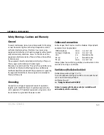
Safety Warnings, cautions and Warranty
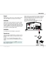
Cables and connections
Cables.longer.than.5.metres.must.be.shielded..All.peripheral.
equipment.must.be.grounded.
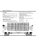
ISDN telephone
100 m 0.22 mm
2
min
Analogue telephone
10 m 0.22 mm
2
min
USB
m
Standard cable
RS-22
m
Standard cable
RS-22
100 m 0.22 mm
2
min
Always follow the installation guidelines described later in this
manual for each type of interface.
Ventilation of the Below Deck Unit
Ambient temperature range: 0 - 45
o
C.
To ensure adequate cooling of the BDU a 10 cm unobstructed
space must be maintained above
and below the unit.
See "
Placing the Below Deck Unit (BDU)
".
Failure to comply with the above rules for installation will
automatically void the warranty.
General
To.avoid.interference,.do.not.run.cables.parallel.to.AC.wiring,.
or.near.fluorescent.lights.or.other.high.magnetic.or.electri-
cal.fields..Interference.from.this.kind.of.sources.causing.
equipment.to.be.faulty.or.fail.working.properly.will.automati-
cally.void.warranty.conditions..Access.to.the.interior.of.the.
equipment.shall.be.made.by.a.Thrane.&.Thrane.AS.qualified.
technician.only.
The equipment should preferably be installed by a Thrane &
Thrane approved Installation & Service Agent.
Warranty.is.not.valid.until.the."Thrane.&.Thrane.AS.Warranty.
Certificate".(at.the.back.of.the.Registration.and.Warranty.
Certificate.booklet.enclosed.with.the.equipment).is.signed.by.
the.approved.Installation.&.Service.Agent,.and.returned.to.
Thrane.&.Thrane.AS.
Grounding
Connection.to.all.type.of.equipment.meant.for.operation.
together.with..SAILOR.33.Fleet+.should.be.done.while.the.
unit.is.powered.off..Peripheral.equipment.using.mains.shall.
be.connected.to.a.grounded.AC.power.socket.
Summary of Contents for SAILOR 33 Fleet+
Page 1: ...F77 USER MANUAL SAILOR 33 Fleet Getting Started ...
Page 2: ......
Page 7: ... GETTING STARTED INTRODUCTION cont d SAILOR 33 Fleet Antenna Unit Parts ...
Page 28: ...28 GETTING STARTED HANDSET FUNCTIONS cont d Date 15 March 2007 Satellite Coverage Map ...
Page 29: ...29 GETTING STARTED HANDSET FUNCTIONS cont d Coverage Map for Each Ocean Region ...
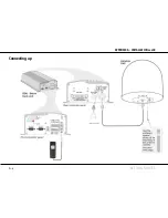
Page 49: ...A APPENDIX A INSTALLATION cont d GETTING STARTED Connecting up ...
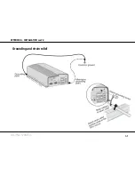
Page 50: ...A APPENDIX A INSTALLATION cont d GETTING STARTED Grounding and strain relief ...
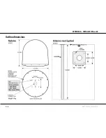
Page 51: ...A APPENDIX A INSTALLATION cont d GETTING STARTED Outline dimensions ...
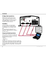
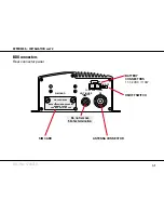
Page 54: ...A APPENDIX A INSTALLATION cont d GETTING STARTED BDU connectors Rear connector panel ...
Page 61: ...A 16 APPENDIX A INSTALLATION cont d GETTING STARTED Serial printer settings ...
Page 67: ...B GETTING STARTED APPENDIX B1 CONNECTING UP BCSiTA V APPENDIX B CONNECTING UP BCSiTA ...
Page 72: ......
Page 73: ......


