A-2
AppendIX A - InStALLAtIOn cont’d
GETTING.STARTED
Location of Antenna unit
Avoiding obstructions
The.antenna.has.a.beamwidth.of.±5
O
.at.3.dB.and.ideally.
requires.a.free.line.of.sight.in.all.directions...
Any.obstruction.will.cause.blind.sectors,.resulting.in.signal.
degradation.or.even.loss.of.communication.with.the.satellite.
Degradation.of.the.satellite.signal.can.only.be.completely.
avoided.by.placing.the.antenna.higher.than.any.obstructions..
This.is.often.not.feasible.and.a.compromise.must.be.made.to.
reduce.the.number.of.blind.sectors.and.cost.of.installation.
The.degree.of.signal.degradation.depends.on.the.size.of.the.
obstructions;.the.distance.to.them.must.therefore.be.consid-
ered.
Preferably,.all.obstructions.within.3.m.of.the.antenna.should.
be.avoided..Obstructions.less.than.15.cm.in.diameter.can.be.
ignored.beyond.this.distance.
Radiation precautions
.
Personnel.should.not.be.ad-
mitted.in.areas.closer.than.
1.m.from.the.antenna..
However,.no.restrictions.
are.required.when.the.
antenna.radome.is.
installed.at.least.2.m.
above.the.highest.point.
accessible.to.passen-
gers.
MICROWAVE RADIATION !
NO ADMITTANCE WITHIN 1 M
Avoiding interference
Do.not.locate.the.Antenna.Unit.close.to.interfering.signal.
sources,.or.in.such.a.position.that.the.source.(e.g..radar.an-
tenna).radiates.directly.into.the..SAILOR.33.Fleet+.antenna.
The.Antenna.Unit.should.be.separated.as.far.as.possible.from.
other.transmitter/receiver.antennas,.and.preferably.by.at.least.
5.m.from.the.antenna.of.other.communication.or.navigation.
equipment,.such.as.the.antenna.of.the.satellite.navigator,.the.
VHF.antenna,.radar.equipment,.or.other.Inmarsat.equipment.
Compass safe distance
For.installation.on.British.or.Norwegian.vessels,.the.antenna.
should.be.located.at.a.distance.of.at.least.1.0.metres.from.the.
magnetic.steering.compass..Be.aware.that.requirements.may.
vary.from.one.country.to.another.
Other precautions
Do.not.place.the.antenna.close.to.the.funnel,.as.smoke.de-
posits.will.then.eventually.degrade.antenna.performance.
The antenna should be installed so that severe vibration and
shock are avoided.
Summary of Contents for SAILOR 33 Fleet+
Page 1: ...F77 USER MANUAL SAILOR 33 Fleet Getting Started ...
Page 2: ......
Page 7: ... GETTING STARTED INTRODUCTION cont d SAILOR 33 Fleet Antenna Unit Parts ...
Page 28: ...28 GETTING STARTED HANDSET FUNCTIONS cont d Date 15 March 2007 Satellite Coverage Map ...
Page 29: ...29 GETTING STARTED HANDSET FUNCTIONS cont d Coverage Map for Each Ocean Region ...
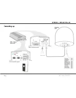
Page 49: ...A APPENDIX A INSTALLATION cont d GETTING STARTED Connecting up ...
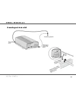
Page 50: ...A APPENDIX A INSTALLATION cont d GETTING STARTED Grounding and strain relief ...
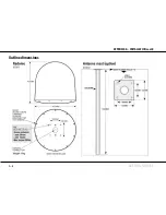
Page 51: ...A APPENDIX A INSTALLATION cont d GETTING STARTED Outline dimensions ...
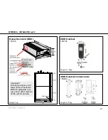
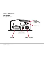
Page 54: ...A APPENDIX A INSTALLATION cont d GETTING STARTED BDU connectors Rear connector panel ...
Page 61: ...A 16 APPENDIX A INSTALLATION cont d GETTING STARTED Serial printer settings ...
Page 67: ...B GETTING STARTED APPENDIX B1 CONNECTING UP BCSiTA V APPENDIX B CONNECTING UP BCSiTA ...
Page 72: ......
Page 73: ......


